Introduction
Flat Pattern Validation in SolidWorks drawings is a critical step in ensuring accurate sheet metal outputs. In many real-world projects, flat pattern views are used directly by manufacturing teams to understand cut profiles, bend positions, and overall geometry. However, these views often contain dimensions that are meant for reference only, not for driving production decisions.
This approach is based on practical engineering workflows developed through real-world SolidWorks drawing validation scenarios. This type of validation approach also connects closely with broader CAD automation workflows used to improve engineering quality and consistency.
The problem is that this validation is usually done manually. Engineers visually inspect drawings, assume correctness, and move forward. In fast-paced environments, this leads to inconsistencies—especially when reference dimensions are not clearly indicated using parentheses. Over time, such small issues can result in confusion, rework, or even incorrect fabrication.
This article focuses on a practical and essential validation approach: checking whether dimensions in flat pattern views are correctly shown as reference values. While flat pattern validation can include many checks, this is one of the most critical and commonly overlooked aspects. The approach discussed here can be applied manually or extended into automation workflows for better consistency and reliability.
What is Flat Pattern Validation in SolidWorks
Flat Pattern Validation in SolidWorks refers to the process of verifying that sheet metal flat pattern views are correctly defined and clearly communicated in drawings. A flat pattern is essentially the unfolded state of a sheet metal part, used primarily for manufacturing processes like laser cutting or punching.
In these views, dimensions are typically not intended to control the model. Instead, they act as reference information to help understand geometry. Because of this, dimensions are usually displayed in parentheses to indicate that they are reference values.

Flat Pattern Validation ensures that:
- The correct flat pattern configuration is used
- Dimensions are displayed appropriately
- The drawing communicates intent clearly to downstream teams
Without validation, even a correctly modeled part can result in a confusing or misleading drawing.
Why Flat Pattern Validation is Important
In theory, drawings should always follow standards. In practice, things are different.
Flat pattern views are often created quickly, especially in production environments. Engineers may focus more on model accuracy and less on how the drawing communicates that information. As a result, validation becomes dependent on individual experience rather than a structured process.

Some common impacts of poor validation include:
- Misinterpretation of dimensions on the shop floor
- Confusion between driving and reference values
- Inconsistent drawing styles across projects
- Increased dependency on manual checking
- Delays during design review and approval
A simple issue like a missing parenthesis around a dimension might not look serious at first. But for a manufacturing team, it can change how the drawing is understood.
Flat Pattern Validation helps eliminate these ambiguities by introducing a repeatable and consistent checking approach.
Common Errors in Flat Pattern Drawings
Even in well-managed projects, certain issues appear repeatedly in flat pattern drawings.

Non-reference dimensions shown as normal dimensions
One of the most frequent problems is when reference dimensions are displayed without parentheses. This makes them look like production-driving values, which can lead to incorrect assumptions.
Inconsistent dimension formatting
Different sheets or views may follow different formatting styles. Some dimensions are shown as reference, while others are not, even within the same drawing.
Flat pattern views not properly verified
In some cases, engineers assume that flat pattern views are correct because the model is correct. However, drawing-level validation is often skipped.
Missing or incomplete dimensions
Flat pattern views may lack essential dimensions required for understanding geometry, especially when generated automatically.
How Flat Pattern Validation Works (System-Level View)
Instead of relying on visual inspection, Flat Pattern Validation can be approached as a structured process.
At a high level, the workflow looks like this:

Drawing → Sheet Scan → View Detection → Dimension Extraction → Validation → Reporting
In simple terms:
- The drawing is taken as input
- All sheets are scanned one by one
- Flat pattern views are identified
- Dimensions from those views are collected
- Each dimension is evaluated based on defined rules
- A result is generated (PASS or FAIL), along with a list of issues
This kind of structured approach removes guesswork. It ensures that validation is consistent, repeatable, and not dependent on who is reviewing the drawing.
This structured validation approach is similar to other CAD automation techniques where design data is systematically checked instead of relying on manual review.
The logic behind this approach is similar to what is implemented in the macro you developed, where flat pattern views are identified and dimensions are checked for correct reference display .
4 Key Checks for Flat Pattern Validation
Flat Pattern Validation can include multiple checks, but in this article, we focus on four practical and essential ones.
1. Flat Pattern View Identification Check
Before validating anything, it is important to ensure that the correct views are being analyzed.
Not all views in a drawing represent flat patterns. Some may be standard model views, section views, or detailed views. Applying validation rules to the wrong view can lead to incorrect conclusions.
This check ensures that only views corresponding to flat pattern configurations are considered for validation.
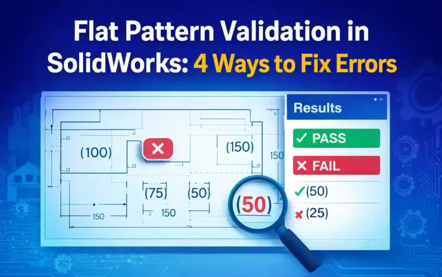
2. REF Dimension (Parentheses) Check
This is the core check discussed in this article.
In flat pattern views, dimensions should typically be displayed as reference values. This is usually indicated by showing them in parentheses.
If a dimension appears without parentheses, it may be interpreted as a driving dimension. This creates confusion, especially for manufacturing teams.
This check verifies whether each dimension in the flat pattern view is displayed correctly as a reference value.
3. Dimension Presence Check
A flat pattern view should contain enough dimensions to clearly communicate geometry.
Sometimes, views are generated automatically or copied from templates, and required dimensions may be missing. This results in incomplete drawings that require additional clarification.
This check ensures that the flat pattern view is not empty or under-defined from a dimensioning perspective.
4. Consistency Check Across Sheets
In multi-sheet drawings, consistency becomes important.
Even if one sheet follows proper formatting, another sheet might not. Differences in dimension styles, reference indication, or layout can create confusion.
This check ensures that the same validation rules are applied across all sheets, maintaining uniformity throughout the drawing.
Similar validation concepts can also be applied to custom properties, metadata, and other drawing elements in SolidWorks automation workflows.
Manual vs System-Based Validation
Flat Pattern Validation can be done manually, but it comes with limitations.
| Aspect | Manual Validation | System-Based Validation |
|---|---|---|
| Speed | Slower | Faster |
| Accuracy | Depends on reviewer | Consistent |
| Repeatability | Low | High |
| Traceability | Limited | Clear reporting |
Manual validation relies heavily on experience and attention to detail. System-based validation, on the other hand, ensures that the same rules are applied every time.
Role in Engineering Compliance Systems
Flat Pattern Validation is not a standalone concept. It can be part of a broader engineering compliance system.
Flat Pattern Validation is one part of a broader engineering validation approach, which can extend to drawing quality checks, metadata validation, and sheet metal verification processes.
In such systems, multiple validation modules work together, including:
- Drawing quality checks
- Metadata validation
- Sheet metal parameter validation
- BOM verification
The REF dimension check discussed here can be seen as one module within this larger framework.
Benefits of Flat Pattern Validation
Implementing even a simple validation approach can provide significant benefits:

- Reduces manual checking effort
- Improves drawing clarity
- Prevents misinterpretation in manufacturing
- Standardizes drawing practices
- Supports future automation initiatives
Future Scope of Flat Pattern Validation
As engineering workflows evolve, validation will move beyond manual checks.
Future improvements may include:
- Automated validation tools with UI dashboards
- Batch processing of multiple drawings
- Integration with PDM systems
- AI-assisted drawing analysis
The approach discussed in this article can act as a starting point for building such systems.
Conclusion
Flat Pattern Validation in SolidWorks is not just about checking drawings—it is about ensuring that engineering intent is clearly communicated.
A simple check, like verifying whether dimensions are shown as reference values, can significantly improve drawing quality. When structured properly, this approach can be extended into larger validation systems that support consistency, reliability, and scalability.
As CAD automation continues to evolve, such validation checks can form the foundation for more advanced engineering quality systems.
This validation approach represents a foundational step toward building scalable engineering compliance systems.
FAQ on Flat Pattern Validation in SolidWorks
1. What is Flat Pattern Validation in SolidWorks?
Flat Pattern Validation in SolidWorks is the process of checking whether flat pattern views in sheet metal drawings are correctly defined and clearly represented, especially in terms of dimension display and drawing clarity.
2. Why is Flat Pattern Validation in SolidWorks important?
Flat Pattern Validation in SolidWorks is important because it ensures that flat pattern drawings are clearly understood during manufacturing. Without proper validation, dimensions and geometry may be misinterpreted on the shop floor.
3. Why are dimensions shown in parentheses in flat pattern drawings?
In Flat Pattern Validation in SolidWorks, dimensions are shown in parentheses to indicate that they are reference values. These values are not intended to drive the model but to help understand geometry in the flat pattern view.
4. What happens if flat pattern dimensions are not shown as reference?
If Flat Pattern Validation in SolidWorks is not followed and reference dimensions are displayed as normal dimensions, they may be misinterpreted as production-driving values, leading to manufacturing errors.
5. How can I perform Flat Pattern Validation in SolidWorks drawings?
Flat Pattern Validation in SolidWorks drawings can be performed by checking whether flat pattern dimensions are displayed as reference values. This can be done manually or using structured validation logic.
6. Can Flat Pattern Validation in SolidWorks be automated?
Yes, Flat Pattern Validation in SolidWorks can be automated using API-based approaches, where dimensions are programmatically checked for correct reference formatting and consistency.
7. Is Flat Pattern Validation in SolidWorks necessary for all sheet metal drawings?
Flat Pattern Validation in SolidWorks is highly recommended for all sheet metal drawings, especially those used for manufacturing, to ensure clarity and consistency.
8. Does Flat Pattern Validation in SolidWorks replace manual drawing checks?
No, Flat Pattern Validation in SolidWorks does not replace manual checks. It supports engineers by making validation more consistent and reducing dependency on visual inspection alone.
9. What are the most common errors identified during Flat Pattern Validation in SolidWorks?
Common issues include:
- Dimensions not shown as reference
- Inconsistent dimension formatting
- Missing dimensions
- Flat pattern views not properly verified
10. Can Flat Pattern Validation in SolidWorks be used in large engineering teams?
Yes, Flat Pattern Validation in SolidWorks is especially useful in large teams where multiple designers work on drawings, helping maintain consistency across projects.
11. Is Flat Pattern Validation in SolidWorks part of a larger CAD quality system?
Yes, Flat Pattern Validation in SolidWorks is typically one part of a broader CAD quality or engineering compliance system, which includes multiple validation checks.
12. How does Flat Pattern Validation in SolidWorks improve drawing quality?
Flat Pattern Validation in SolidWorks improves drawing quality by ensuring that dimensions are clearly represented, reducing ambiguity and improving communication between design and manufacturing teams.
13. What is the difference between reference and driving dimensions in Flat Pattern Validation in SolidWorks?
In Flat Pattern Validation in SolidWorks, reference dimensions are used for information only and are shown in parentheses, while driving dimensions control the model geometry.
14. Can Flat Pattern Validation in SolidWorks reduce manufacturing errors?
Yes, Flat Pattern Validation in SolidWorks helps reduce manufacturing errors by ensuring that drawings are interpreted correctly and that dimensions are clearly identified as reference values.
15. How can Flat Pattern Validation in SolidWorks support future automation systems?
Flat Pattern Validation in SolidWorks provides a structured approach that can be extended into automation systems, enabling consistent and repeatable validation across multiple drawings.