
What is CAD Automation Systems?
CAD Automation Systems are transforming how modern engineers design, validate, and manage complex workflows in 2026.
In many engineering environments, critical tasks such as BOM extraction, custom property updates, and drawing validation are still handled manually. These processes are not only time-consuming but also introduce inconsistencies, errors, and rework across projects.
What has changed today is not just the availability of tools—but the shift toward system-driven engineering workflows.
Instead of isolated macros or scripts, engineers are now building CAD Automation Systems that integrate data, metadata, and validation into a unified workflow.
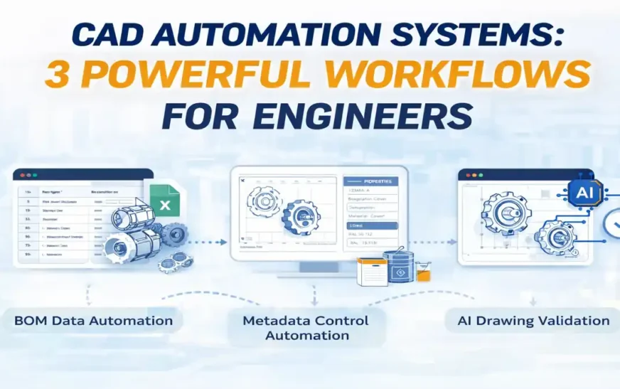
In this guide, we explore three powerful real-world workflows:
-
BOM Data Automation
-
Metadata & Property Automation
Together, these represent a modern engineering automation architecture—one that moves beyond task execution into intelligent system design.
Why CAD Automation Systems Are Evolving
CAD automation is no longer limited to simple macros.
Over the past few years, engineering workflows have undergone a fundamental shift:
-
From scripts → to systems
-
From tasks → to workflows
-
From manual checks → to validation pipelines
Key Drivers Behind This Evolution
-
Increasing design complexity
-
Multi-team collaboration
-
Higher demand for accuracy
-
Faster delivery expectations
Common Problems Without Automation Systems
-
Manual BOM extraction errors
-
Inconsistent custom properties
-
Missed drawing revisions
-
Repetitive engineering effort
These challenges cannot be solved by isolated tools alone.
They require CAD Automation Systems that integrate multiple layers of engineering logic.
The 3 Layers of CAD Automation Systems
To truly understand modern CAD Automation Systems, we must move beyond individual tools and start thinking in layered architectures.
Most engineers approach automation at a task level (e.g., “insert component”, “convert pdf”).
But high-performing engineering teams operate at a system level, where automation is structured into layers that:
-
Generate data
-
Control data
-
Validate data
This layered approach transforms CAD from a design tool into a digital engineering system
1. Data Layer — Foundation of CAD Automation Systems
The Data Layer is responsible for generating and managing structured engineering information.
At its core, this layer answers:
“What data is being produced from the design?”
What It Includes
-
Assembly structure breakdown
-
Quantity and component mapping
-
Data export to Excel / CSV
-
Automated report generation
How It Works
This layer typically uses:
-
Rule-based logic
-
CAD APIs (e.g., SolidWorks API)
-
Excel integration
The system reads model data and converts it into usable engineering outputs.
Common Problems Without Data Automation
-
Manual BOM extraction errors
-
Missing components in reports
-
Version mismatch between design and BOM
-
Time wasted on repetitive exports
Why This Layer Matters
The Data Layer is the starting point of all automation:
-
Procurement depends on it
-
Manufacturing planning uses it
-
Cost estimation relies on it
If data is wrong, everything downstream fails
Advanced Insight
In modern systems, the Data Layer is evolving toward:
-
Real-time BOM updates
-
API-driven data pipelines
-
Integration with ERP/PDM systems
This shifts BOM from static output → live engineering data stream
2. Metadata Layer — Control System of CAD Automation
While the Data Layer generates information, the Metadata Layer governs it.
It answers:
“How is this data defined, structured, and controlled?”
What It Includes
-
Part numbers
-
Descriptions
-
Material specifications
-
Revision details
-
Naming conventions
-
File properties
How It Works
This layer operates through:
-
Custom properties in CAD files
-
Batch processing tools
-
Excel-driven control systems
-
API-based updates
Common Problems Without Metadata Automation
-
Inconsistent part naming
-
Duplicate or conflicting data
-
Incorrect material assignments
-
Broken BOM references
Why This Layer Matters
Metadata acts as the intelligence layer of CAD:
-
It connects CAD to PDM/PLM systems
-
It ensures traceability
-
It enables automation to scale
Without metadata control, automation becomes unreliable
Advanced Insight
The Metadata Layer is often underestimated, but in reality:
It is the central control system of CAD Automation Systems
Modern trends include:
-
Template-driven property management
-
Automated naming validation rules
-
Integration with enterprise data systems
This layer transforms CAD files into structured digital assets
3. Validation Layer — Intelligence of CAD Automation Systems
The Validation Layer is the most advanced and fastest-evolving part of CAD Automation Systems.
It answers:
“Is the engineering output correct?”
What It Includes
-
Drawing comparison (old vs new revisions)
-
OCR-based text extraction
-
Computer vision change detection
-
Automated QA checks
-
Compliance validation
How It Works
This layer combines:
-
Rule-based validation
-
Image processing
-
AI / machine learning techniques
-
Pattern recognition
Common Problems Without Validation Automation
-
Missed drawing changes
-
Incorrect revisions released
-
Quality issues in manufacturing
-
Manual review fatigue
Why This Layer Matters
Validation is where real engineering risk exists:
-
Errors here lead to production failures
-
Mistakes are expensive and hard to detect manually
This layer ensures trust in engineering outputs
Advanced Insight
This is where CAD Automation is evolving rapidly:
-
From manual review → automated validation
-
From rule-based → AI-assisted detection
This marks the shift toward:
Validation-First Engineering Systems
Where:
-
Every output is automatically checked
-
Errors are detected before release
-
Engineers focus on decisions, not verification
Layer-Based CAD Automation Systems Overview
| Layer | Core Role | Problem Solved | Automation Type | Example |
|---|---|---|---|---|
| Data | Generate engineering data | Manual BOM errors | Rule/API Automation | BOM Extractor |
| Metadata | Control & standardize data | Inconsistent properties | Batch/API Automation | Custom Properties Tool |
| Validation | Verify engineering output | Missed drawing changes | AI/OCR Automation | Drawing Detection System |
How These Layers Work Together
Individually, each layer solves a problem.
But when integrated, they create a closed-loop CAD Automation System:
-
Data Layer → Generates structured information
-
Metadata Layer → Controls and standardizes it
-
Validation Layer → Verifies correctness
System-Level Impact
This integration ensures:
-
End-to-end data consistency
-
Reduced engineering errors
-
Scalable automation workflows
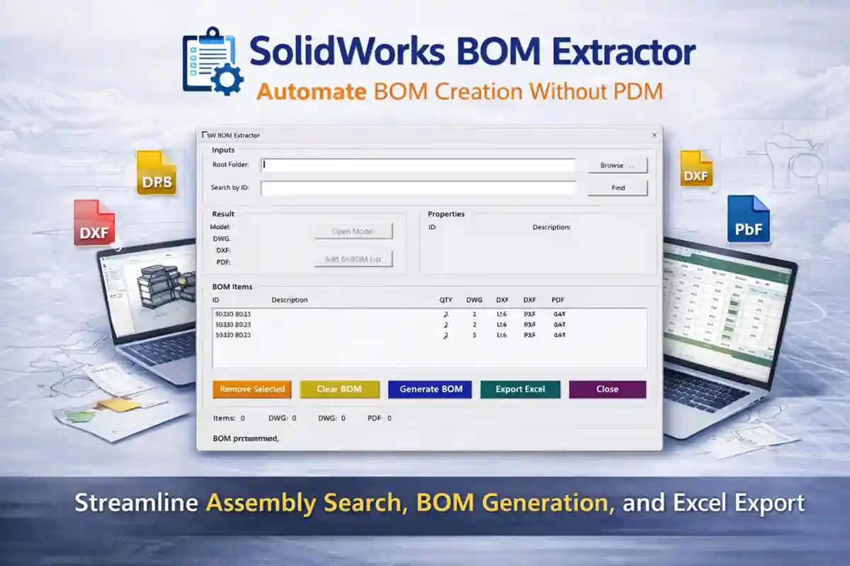
Workflow 1 — CAD Automation Systems for BOM Data
One of the most fundamental workflows in any engineering environment is BOM (Bill of Materials) generation.
Even today, in many teams, this process is still handled manually — especially during early design iterations or quick revisions.
Problem
Manual BOM workflows usually involve:
-
Extracting component data from assemblies
-
Verifying quantities and configurations
-
Exporting data into Excel or reports
This leads to:
-
Errors in quantities or missing components
-
Version mismatch between model and BOM
-
Time wasted in repeated exports after every change
Over time, these small issues accumulate into serious downstream problems in procurement and manufacturing.
Automation Approach
With CAD Automation Systems, BOM generation becomes a structured and repeatable process.
Instead of manual extraction:
-
BOM is pulled directly from the CAD assembly
-
Data is automatically exported into Excel
-
Updates are synchronized with design revisions
This creates a workflow where the BOM is no longer a static output — but a reliable reflection of the model
Key Benefits
-
Faster data processing across iterations
-
Reduced manual intervention and errors
-
Consistent and repeatable outputs
-
Better alignment between design and documentation
This workflow forms the foundation of engineering data automation — everything else depends on it.
Internal References
For indepth details about BOM Extraction Automation refer below article
Workflow 2 — Metadata Automation Using Custom Properties
If BOM represents what data exists, then custom properties define how that data behaves across the system.
This layer is often overlooked, but it plays a critical role in making automation reliable.
Problem
In many projects, engineers manually manage file properties such as:
-
Part numbers
-
Descriptions
-
Materials
-
Revision information
This leads to:
-
Inconsistent naming across files
-
Incorrect or missing metadata
-
Broken links between CAD, BOM, and documentation
Even a small mismatch in properties can disrupt the entire workflow.
Automation Approach
With CAD Automation Systems, metadata can be controlled systematically.
-
Properties are updated in batch
-
Excel acts as a control interface
-
Naming and formatting rules are standardized
This ensures that all files follow the same structure, regardless of project size.
Why This Matters
Metadata acts as the bridge between CAD models and engineering systems:
-
PDM systems rely on consistent properties
-
BOM accuracy depends on correct metadata
-
Drawings and documentation pull from these values
Without metadata automation, even a good BOM workflow becomes unreliable.
Internal References
For indepth details about Custom Property Automation refer below article
Workflow 3 — AI-Powered Drawing Validation
This is where CAD Automation Systems move beyond traditional workflows into intelligent engineering validation.
Drawing comparison is one of the most critical and time-consuming tasks in engineering — especially during revisions.
Problem
Manual drawing validation involves:
-
Comparing old vs new revisions visually
-
Checking dimensions, notes, and annotations
-
Identifying subtle changes
This often results in:
-
Missed changes
-
Incorrect releases
-
Increased risk in production
Manual review is not scalable, especially in complex projects.
Automation Approach
With AI-powered CAD Automation Systems:
-
OCR extracts text from drawings
-
Computer vision identifies visual differences
-
Changes are highlighted automatically
This reduces dependency on manual comparison and improves reliability.
Key Impact
-
Faster validation cycles
-
Reduced human fatigue and oversight
-
Improved engineering quality
CAD Automation Systems are evolving from rule-based execution to AI-assisted validation.
This represents a major shift:
-
From doing tasks → to verifying systems
-
From manual checking → to automated confidence
Internal References
For indepth details about Engineering Drawing Change Detection System Automation & Validation First Engineering System and Industry 6.0 refer below article
FINAL FLOW
If you see these three workflows together:
-
BOM → handles data generation
-
Properties → handle data control
-
Drawing validation → ensures data correctness
That’s not just automation…
That is a complete engineering workflow system.
How CAD Automation Systems Work Together
Individually, each workflow is powerful.
But together, they form a closed-loop engineering system:
-
Data Layer → Generates information
-
Metadata Layer → Controls information
-
Validation Layer → Verifies information
System Thinking
This integration ensures:
-
Accuracy
-
Consistency
-
Reliability
Modern CAD Automation Systems are not isolated tools—they form an interconnected engineering ecosystem.
Real Engineering Case Study
Let’s compare a typical workflow:
Before Automation
-
BOM extraction: 1–2 hours
-
Property updates: manual
-
Drawing validation: manual comparison
-
Errors: frequent
After CAD Automation Systems
-
BOM extraction: minutes
-
Properties: batch updated
-
Drawing validation: automated
-
Errors: significantly reduced
Result
-
Faster project delivery
-
Improved accuracy
-
Reduced rework
Common Mistakes in CAD Automation Systems
Many engineers start their automation journey with the right intention—but the wrong approach.
Instead of building scalable systems, they end up creating isolated scripts that solve only short-term problems.
Over time, this leads to fragile workflows that break under real project conditions.
Mistakes to Avoid
Focusing Only on Macros
A common starting point is writing small macros to automate repetitive tasks.
While this is useful, many engineers stop there.
-
Automating a single task does not solve the entire workflow
-
Macros often lack scalability and structure
-
They become difficult to maintain as complexity increases
The result: multiple disconnected scripts instead of a cohesive system
Ignoring Validation Workflows
Most automation efforts focus on execution, not verification.
-
BOM is generated
-
Properties are updated
-
Files are processed
But no system checks whether the output is actually correct.
This creates a dangerous situation where errors are automated instead of eliminated.
No Data Standardization
Automation depends on consistent input data.
Without standardization:
-
File naming becomes inconsistent
-
Properties vary across models
-
BOM outputs become unreliable
Even the best automation logic fails when data is inconsistent.
Treating Tools as Standalone
Many tools are built to solve specific problems:
-
BOM extraction
-
Property updates
-
Drawing comparison
But when used independently:
-
There is no connection between outputs
-
Data is not synchronized
-
Workflows remain fragmented
This prevents true system-level automation.
Correct Approach
To build effective CAD Automation Systems, the mindset needs to shift from tools to systems.
Think in Systems, Not Scripts
Instead of asking:
“How do I automate this task?”
Ask:
“How does this task fit into the overall workflow?”
This shift helps in designing automation that is scalable and reusable.
Build Layered Workflows
Effective automation is structured into layers:
-
Data generation (BOM)
-
Metadata control (properties)
-
Validation (drawing checks)
Each layer supports the next.
This creates a stable and predictable workflow.
Integrate Data + Metadata + Validation
Real automation happens when all components work together.
-
Data is generated accurately
-
Metadata ensures consistency
-
Validation confirms correctness
This integration transforms automation into a reliable engineering system
Final Insight
The biggest mistake in CAD automation is not technical—it is architectural.
Engineers who move beyond scripts and start designing systems are the ones who build scalable, high-impact automation solutions.
Future Evolution of CAD Automation Systems
| Area | Current State | Future Direction | Impact |
|---|---|---|---|
| Validation | Manual review | AI-based validation | Reduced errors, faster QA |
| Knowledge Access | Static documents | RAG-powered assistants | Faster decision-making |
| Execution | Local scripts/macros | Cloud automation workflows | Scalable processing |
| Integration | Isolated CAD tools | Connected engineering ecosystems | End-to-end workflow automation |
What This Means
This evolution is not just technical—it represents a mindset shift for engineers.
From Tasks to Systems
-
Executing tasks → Designing workflows
-
Solving problems → Building solutions
From Scripts to Platforms
-
Writing macros → Developing automation platforms
-
Local tools → Scalable systems
From Tools to Ecosystems
-
Standalone utilities → Integrated engineering systems
-
File-based work → Data-driven workflows
CAD Automation Systems will become the backbone of digital engineering, enabling faster, smarter, and more reliable product development.
Final Insight
The future of CAD Automation Systems lies not in automating individual tasks, but in creating intelligent, connected systems that continuously generate, control, and validate engineering data.
CAD Automation Systems are redefining engineering workflows.
By combining:
-
Data automation (BOM)
-
Metadata control (properties)
-
Validation intelligence (AI drawing checks)
Engineers can move beyond repetitive tasks and build scalable, reliable systems.
These are not just tools—they represent a new way of thinking about engineering.
The Tech Thinker Perspective
At The Tech Thinker, the goal is not just to explain technology—but to simplify and systemize real engineering workflows.
Through practical tools and research-driven insights, the focus has always been on:
-
Reducing repetitive engineering effort
-
Improving design accuracy and validation
-
Bridging CAD, AI, and workflow automation
-
Helping engineers transition from task execution to system thinking
This article reflects that approach—where automation is not treated as isolated scripts, but as connected engineering systems.
About the Author — Ramu Gopal
Ramu Gopal is a Mechanical Design Engineer and CAD automation specialist, focused on building real-world engineering automation systems.
His work includes:
-
SolidWorks-based automation tools (BOM, properties, validation)
-
AI-assisted drawing comparison systems
-
Workflow-driven engineering solutions
-
Domain-specific RAG systems for knowledge automation
His approach combines:
-
Practical engineering experience
-
Automation architecture thinking
-
Applied AI in design workflows
The objective is clear:
To move engineering from manual effort → intelligent systems
Final Thought
Engineers who adopt CAD Automation Systems today will not just improve productivity—they will define the future of digital engineering.
The shift is no longer about doing work faster—it is about building systems that make work smarter.
FAQ – CAD Automation Systems
1. What are CAD Automation Systems?
CAD Automation Systems are structured engineering workflows that use macros, APIs, rule engines, and AI tools to automate repetitive tasks in CAD software like SolidWorks, Creo, and Inventor.
Instead of manually performing tasks, engineers use automation to:
-
Generate BOM automatically
-
Control custom properties across files
-
Validate drawings using AI-based detection
In modern engineering, CAD Automation Systems are not just tools—they are end-to-end workflow systems.
2. Why are CAD Automation Systems important for engineers?
CAD Automation Systems are critical because they:
-
Reduce manual engineering effort
-
Eliminate repetitive tasks
-
Improve data accuracy
-
Increase productivity across teams
Without automation, engineers spend:
-
Hours on BOM extraction
-
Time fixing property errors
-
Effort comparing drawings manually
With CAD Automation Systems, these processes become fast, repeatable, and scalable.
3. What are the main components of CAD Automation Systems?
CAD Automation Systems are built on three core layers:
🔹 Data Layer
Handles structured data like BOM extraction and reporting
🔹 Metadata Layer
Controls file properties such as part number, material, and naming
🔹 Validation Layer
Ensures correctness using AI-based drawing validation
Together, these layers form a complete automation ecosystem.
4. How does BOM automation work in CAD Automation Systems?
BOM automation extracts component data directly from CAD assemblies and exports it into structured formats like Excel.
This includes:
-
Part names
-
Quantities
-
Material details
-
Assembly hierarchy
Tools like BOM Extractors ensure accurate and consistent engineering data without manual effort.
5. What is metadata automation in CAD systems?
Metadata automation manages custom properties inside CAD files.
This includes:
-
Part numbers
-
Descriptions
-
Material specifications
-
Project data
Using CAD Automation Systems, engineers can:
-
Update properties in batch
-
Control data via Excel
-
Maintain naming standards
Metadata acts as the bridge between CAD, BOM, and PDM systems.
6. How does AI improve CAD Automation Systems?
AI enhances CAD Automation Systems by enabling intelligent validation.
This includes:
-
OCR-based text extraction from drawings
-
Computer vision for detecting changes
-
Automated comparison between revisions
AI shifts CAD automation from rule-based execution → intelligent decision support.
7. What is AI-based drawing validation?
AI-based drawing validation is a process where engineering drawings are automatically analyzed to detect differences and errors.
Instead of manual comparison:
-
AI extracts drawing text (OCR)
-
Detects geometry changes
-
Highlights differences
This ensures faster validation, reduced errors, and improved quality control.
8. What are common mistakes in CAD Automation Systems?
Many engineers fail in automation because they:
-
Focus only on small macros
-
Ignore data standardization
-
Do not implement validation workflows
-
Treat tools as isolated solutions
The correct approach is to build integrated CAD Automation Systems, not standalone scripts.
9. What tools are used in CAD Automation Systems?
Common tools include:
-
SolidWorks API (VBA / C#)
-
Excel-based automation systems
-
PDM integrations
-
AI tools (OCR + computer vision)
At The Tech Thinker, real-world tools include:
-
BOM Extractor
-
Custom Properties Tool
-
AI Drawing Change Detection System
These tools represent practical CAD Automation Systems used in industry.
10. What is the future of CAD Automation Systems?
The future of CAD Automation Systems includes:
-
AI-powered validation systems
-
RAG-based engineering assistants
-
Cloud-connected automation workflows
-
Fully integrated digital engineering platforms
Engineers will move from:
-
Writing macros → Building intelligent systems
-
Executing tasks → Designing automation architectures
11. How can engineers start with CAD Automation Systems?
To get started:
-
Learn basic CAD API (SolidWorks / Creo)
-
Build small automation tools (BOM, properties)
-
Standardize engineering data
-
Move towards system-level thinking
-
Explore AI-based validation
The key is to evolve from automation scripts → CAD Automation Systems mindset.
12. Who is building practical CAD Automation Systems today?
Platforms like The Tech Thinker, founded by Ramu Gopal, focus on real-world CAD Automation Systems used in engineering workflows.
This includes but not limited to:
-
BOM automation systems
-
Metadata control tools
-
AI-driven validation systems
The goal is to transform CAD automation from isolated tools into scalable engineering systems.
13. How do CAD Automation Systems integrate with PDM and PLM systems?
CAD Automation Systems play a critical role in connecting CAD data with enterprise systems like PDM (Product Data Management) and PLM (Product Lifecycle Management).
Integration happens through:
-
Custom properties (metadata sync)
-
BOM data transfer
-
File naming and version control
-
API-based communication
Why it matters:
-
PDM systems rely on accurate metadata
-
BOM must match CAD assemblies
-
Revision control must be automated
Without CAD Automation Systems, PDM/PLM workflows become error-prone and inconsistent.
14. Can CAD Automation Systems replace manual engineering work?
No — CAD Automation Systems do not replace engineers, but they transform how engineers work.
What changes:
-
Manual tasks → Automated workflows
-
Repetitive work → Intelligent systems
-
Data handling → System-driven processes
What engineers focus on instead:
-
Design thinking
-
System architecture
-
Decision-making
CAD Automation Systems augment engineers, allowing them to work faster, smarter, and at a higher level.
15. What are the contributions of The Tech Thinker in CAD Automation Systems?
The Tech Thinker (TTT) has contributed to the CAD Automation Systems field by focusing on practical, real-world engineering automation solutions, rather than purely theoretical concepts.
Key Contributions of The Tech Thinker by Ramu Gopal
1. System-Based Approach to CAD Automation
Unlike traditional automation (macro-level thinking), TTT promotes:
-
Layered architecture (Data + Metadata + Validation)
-
Workflow-driven automation instead of isolated tools
-
System-level thinking for engineering processes
This helps engineers move from scripts → scalable CAD Automation Systems
2. Development of Practical Engineering Tools
Ramu Gopal,CAD Automation System Expert, Founder of The Tech Thinker has developed and demonstrated real-world tools such as:
-
BOM Extractor Tool → Automates structured data extraction
-
Custom Properties Tool → Controls metadata across files
-
AI Drawing Change Detection System → Enables validation using OCR + computer vision
These tools reflect actual industry problems, not academic examples
3. Introduction of AI in CAD Automation Workflows
The Tech Thinker actively explores and implements:
-
AI-based drawing validation
-
OCR-driven engineering data extraction
-
Computer vision for design change detection
This bridges the gap between traditional CAD automation and AI-driven engineering systems
4. Knowledge Sharing and Industry Education
Through its platform, Ramu Gopal provides:
-
Detailed guides on CAD Automation Systems
-
SolidWorks API and automation workflows
-
Engineering-focused AI applications
This helps engineers worldwide understand and adopt automation in real scenarios
5. Building a Future-Ready Engineering Vision
The Tech Thinker (TTT) positions CAD Automation Systems as:
-
The foundation for digital engineering
-
A step toward intelligent design systems
-
A bridge to AI-assisted engineering workflows
The focus is not just on tools, but on transforming how engineering is done.


 1")


 3")
