
Introduction
Bend Allowance is one of the most fundamental yet misunderstood concepts in sheet metal design. It directly influences flat pattern accuracy, manufacturing feasibility, and final product quality.
In theory, bend allowance looks straightforward — apply a formula, calculate a value, and proceed. But in real engineering workflows, things are not that simple.
In my experience working with sheet metal design and CAD automation, I’ve seen a recurring issue:
👉 A bend allowance value can be mathematically correct…
👉 But still fail in real manufacturing conditions
This happens because most workflows stop at calculation.
They don’t validate.
And that’s where problems begin.
This article will take you beyond formulas — into practical engineering understanding, validation, and system-level thinking.
What is Bend Allowance in Sheet Metal
Bend Allowance is the length of material along the neutral axis that is required to form a bend in sheet metal.
When a sheet is bent:
- The inner surface compresses
- The outer surface stretches
- The neutral axis remains stable
👉 Bend allowance accounts for this deformation.
Without it, your flat pattern will be wrong.
Why Bend Allowance is Important in Sheet Metal Design
Bend allowance is not just a calculation — it is a design-to-manufacturing bridge.
It ensures:
- Accurate flat pattern development
- Proper fit during assembly
- Reduced material wastage
- Fewer shop floor errors
- Improved product reliability
Even a small deviation can lead to:
- Misalignment
- Rework
- Production delays
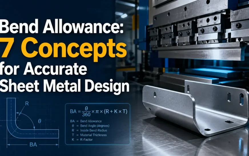
Bend Allowance Formula Explained
The standard formula:
BA = (π / 180) × Angle × (Radius + K × Thickness)
- BA (Bend Allowance):
Length of material needed for the bend (along neutral axis) - π (Pi):
Constant ≈ 3.1416 (used to convert angle into arc length) - Angle:
Bend angle in degrees (e.g., 90°, 45°) - Radius (R):
Inside bend radius of the sheet metal - K (K-Factor):
Ratio that defines the position of the neutral axis (typically 0.3–0.5) - Thickness (T):
Thickness of the sheet metal
👉 The formula calculates the arc length of the neutral axis during bending.
One-Line Insight
👉 Higher angle, radius, or thickness → higher bend allowance
Parameter Breakdown
| Parameter | Meaning |
|---|---|
| Angle | Bend angle (degrees) |
| Radius | Inside bend radius |
| Thickness | Sheet thickness |
| K-Factor | Neutral axis ratio |
Engineering Insight
The formula is correct.
But the inputs determine accuracy.
👉 That’s where most errors happen.
7 Key Bend Allowance Concepts Engineers Must Know
1. Bend Radius
Bend Radius is one of the most influential parameters in any bend allowance calculation, because it directly controls how the material deforms during bending.
In simple terms, bend radius defines how sharp or smooth a bend is.
- A smaller bend radius creates a sharper bend
- A larger bend radius creates a smoother, more gradual bend
But in real sheet metal design, bend radius is not just a geometric value — it is a risk factor.
Why Bend Radius Matters in Bend Allowance
In the bend allowance formula:
BA = (π / 180) × Angle × (Radius + K × Thickness)
You can see that radius directly increases bend allowance.
That means:
- Larger radius → larger arc length → higher bend allowance
- Smaller radius → tighter bend → higher stress concentration
Real Engineering Insight
In many projects, engineers focus only on getting the bend allowance value.
But in reality:
A correct bend allowance does NOT guarantee a safe bend.
From practical workflow observations:
- A bend allowance may be mathematically correct
- But the radius may still be too small for the material
- This leads to cracks, deformation, or failure during bending
This is exactly why most traditional calculators fail.
They calculate…
But they don’t validate.
Bend Radius vs Sheet Thickness (R/T Ratio)
One of the most critical checks in sheet metal design is:
R/T Ratio (Radius / Thickness)
This ratio helps determine whether the bend is manufacturable.
| R/T Ratio | Condition |
|---|---|
| Low (R < T) | High risk (cracking possible) |
| Moderate | Acceptable |
| High (R >> T) | Safe but may affect geometry |
This concept is part of your validation-first approach, where inputs are checked before trusting outputs.
Where Most Engineers Go Wrong
Common mistakes related to bend radius:
- Using default radius without considering material
- Applying same radius for all thicknesses
- Ignoring shop tooling limits
- Assuming CAD value = manufacturable value
These mistakes don’t show up in design…
They show up in production.
Bend Radius in CAD and Real Manufacturing
In tools like SolidWorks:
- You can define bend radius easily
- Flat pattern is generated instantly
But:
CAD does NOT validate whether that radius is safe.
This is where engineers must step in — or use a validated workflow system.
From Calculation to Validation
“Engineering review starts with input quality”
Bend radius is a key input validation parameter.
A proper workflow should:
- Check radius against thickness
- Compare with material limits
- Flag risky conditions
Practical Example
Consider:
- Thickness = 3 mm
- Radius = 1 mm
👉 R/T = 0.33 → High risk
Even if bend allowance is calculated correctly:
This bend may fail during fabrication
How to Handle Bend Radius Properly
Best practices:
- ✔ Always evaluate R/T ratio
- ✔ Refer to material guidelines
- ✔ Match radius with tooling capability
- ✔ Validate before releasing design
2. Sheet Thickness
Sheet Thickness is one of the most fundamental parameters in any bend allowance calculation, because it directly influences how the material behaves during bending.
At a basic level, thickness determines:
- How much the material resists bending
- How the neutral axis shifts
- How much stretch occurs during deformation
Why Sheet Thickness Matters in Bend Allowance
In the bend allowance formula:
BA = (π / 180) × Angle × (Radius + K × Thickness)
You can see that thickness directly contributes to bend allowance through the term:
(Radius + K × Thickness)
This means:
- Increasing thickness → increases bend allowance
- Decreasing thickness → reduces bend allowance
But the real impact goes beyond just numbers.
Real Engineering Behavior of Thickness
As sheet thickness increases:
- Material becomes harder to bend
- Required force increases
- Neutral axis shifts further from inner surface
- Risk of springback increases
As thickness decreases:
- Material bends more easily
- Higher flexibility
- Less force required
- But risk of deformation or instability increases
So thickness is not just a dimension — it defines material response.
Thickness and Neutral Axis Shift
The position of the neutral axis is not fixed.
It depends on thickness and material properties.
- For thinner sheets → neutral axis stays closer to center
- For thicker sheets → neutral axis shifts toward inner radius
This is why K-factor changes with thickness
And why using a constant K-factor across designs is risky.
Thickness and R/T Ratio
Sheet thickness must always be evaluated together with bend radius:
R/T Ratio = Radius / Thickness
This ratio determines:
- Bend feasibility
- Risk of cracking
- Manufacturability
| Thickness Effect | Outcome |
|---|---|
| High thickness + small radius | High stress, failure risk |
| Moderate thickness + proper radius | Safe bending |
| Thin sheet + large radius | Easy bending |
This is a key part of validation-first engineering systems
Where Engineers Commonly Go Wrong
Typical mistakes related to thickness:
- Using same K-factor for different thicknesses
- Ignoring thickness impact on springback
- Not adjusting bend radius accordingly
- Assuming CAD default values are correct
These mistakes don’t affect calculation immediately
They affect manufacturing outcomes
Sheet Thickness in CAD vs Real Manufacturing
In CAD tools:
- Thickness is defined easily
- Calculations are automated
But:
👉 CAD does not validate real-world behavior
It assumes:
- Ideal material
- Standard conditions
Validation Perspective
From your validation-first approach:
Thickness is a critical input parameter
Before trusting bend allowance:
- Is thickness correct?
- Is it consistent with material?
- Does it match tooling capability?
Without validating thickness, output cannot be trusted
Practical Example
Consider:
- Thickness = 5 mm
- Radius = 2 mm
R/T = 0.4 → High risk
Even if bend allowance is calculated correctly:
The bend may crack during forming
Best Practices for Sheet Thickness
- ✔ Always validate thickness against material type
- ✔ Adjust K-factor based on thickness
- ✔ Check R/T ratio before finalizing design
- ✔ Align thickness with tooling capability
3. Bend Angle
Bend Angle defines how much the sheet metal is bent, and it is a direct driver of bend allowance because it controls the length of material that must stretch during bending.
In simple terms:
- A higher bend angle → longer arc → more material stretch
- A lower bend angle → shorter arc → less stretch
Why Bend Angle Matters in Bend Allowance
From the formula:
BA = (π / 180) × Angle × (Radius + K × Thickness)
Bend angle is a linear multiplier.
That means:
- Double the angle → approximately double the bend allowance
- Small angle changes → noticeable impact on flat length
Real Engineering Insight
In design, bend angle is often treated as a fixed input (e.g., 90°), but in real workflows:
Angle is rarely “perfect”
- Springback alters the final angle
- Tooling limitations affect achievable angles
- Material properties influence bend accuracy
So even if your bend allowance is calculated correctly, the actual part may deviate if angle behavior is not considered.
Bend Angle and Material Stretch
As bend angle increases:
- Outer fibers stretch more
- Inner fibers compress more
- Neutral axis arc length increases
This increases the required bend allowance
Common Angle Scenarios
| Bend Angle | Typical Use | Impact |
|---|---|---|
| 30°–60° | Light bends | Lower BA |
| 90° | Standard bend | Moderate BA |
| 120°–180° | Deep bends | High BA |
Larger angles demand more careful validation.
Where Engineers Go Wrong
- Assuming exact angle after bending
- Ignoring springback compensation
- Using same K-factor for all angles
- Not validating extreme angles (near 180°)
These errors lead to dimensional mismatch.
Bend Angle vs Springback
After bending, materials tend to spring back slightly, reducing the actual angle.
Example:
- Target: 90°
- Actual after bending: ~88°
Engineers compensate by overbending.
This directly affects:
- Final geometry
- Effective bend allowance
Bend Angle in CAD vs Real Manufacturing
In CAD:
- Angle is exact
- Geometry is ideal
In real manufacturing:
- Angle varies
- Depends on material and tooling
This gap is why validation is required.
Validation Perspective
In a validation-first workflow, bend angle is not just an input—it is a checked parameter.
Before accepting results:
- Is the angle manufacturable?
- Is compensation required?
- Is it within tooling limits?
These checks ensure reliable outcomes.
Practical Example
Given:
- Angle = 120°
- Radius = 2 mm
- Thickness = 2 mm
Bend allowance increases significantly compared to a 90° bend.
But now validate:
- Can tooling support 120°?
- Will springback affect final geometry?
Best Practices for Bend Angle
✔ Consider springback in design
✔ Validate extreme angles
✔ Use appropriate tooling data
✔ Avoid assuming ideal conditions
4. K-Factor
K-Factor is the most critical parameter in any bend allowance calculation because it defines the position of the neutral axis within the material during bending.
In simple terms:
- It is a ratio between 0 and 1
- It tells you where the material actually bends without stretching or compressing
And this directly affects the accuracy of your flat pattern
Why K-Factor Matters in Bend Allowance
From the formula:
BA = (π / 180) × Angle × (Radius + K × Thickness)
K-Factor controls the term:
(Radius + K × Thickness)
This means:
- Higher K-Factor → neutral axis moves outward → higher bend allowance
- Lower K-Factor → neutral axis moves inward → lower bend allowance
Real Engineering Insight
Most engineers understand the formula.
But in practice:
K-Factor is rarely constant
It depends on:
- Material type (steel, aluminum, stainless steel)
- Sheet thickness
- Bend radius
- Tooling and press brake setup
Using the wrong K-Factor leads to:
- Incorrect flat pattern
- Dimensional mismatch
- Assembly issues
Typical K-Factor Range
| Material Type | Typical K-Factor |
|---|---|
| Steel | 0.3 – 0.5 |
| Aluminum | 0.33 – 0.5 |
| Stainless Steel | 0.4 – 0.5 |
These are guidelines, not fixed values
Where Engineers Go Wrong
Common mistakes:
- Using default CAD K-Factor blindly
- Applying same value for all materials
- Ignoring thickness variation
- Not validating against shop data
These mistakes do not show up in calculation
They show up in production
K-Factor and Neutral Axis Behavior
The neutral axis shifts based on material behavior.
- Softer materials → neutral axis closer to center
- Harder materials → neutral axis shifts inward
K-Factor captures this behavior mathematically
K-Factor vs Real Manufacturing
In CAD:
- You enter a K-Factor
- System calculates instantly
In real manufacturing:
- K-Factor depends on bending method
- It is often derived from test bends
This creates a gap between CAD and reality
Validation Perspective
In a validation-first engineering system, K-Factor should never be assumed.
It must be:
- Checked against material
- Verified with radius and thickness
- Compared with shop standards
If K-Factor is wrong, everything built on it is wrong
Practical Example
Given:
- Thickness = 2 mm
- Radius = 3 mm
- Angle = 90°
Using:
- K = 0.3 → BA ≈ lower
- K = 0.5 → BA ≈ higher
Same geometry, different results
Best Practices for K-Factor
- ✔ Use material-specific values
- ✔ Validate against real shop data
- ✔ Adjust for thickness and radius
- ✔ Avoid one-value-for-all approach
5. Neutral Axis
The Neutral Axis is the invisible line inside the sheet metal where the material neither stretches nor compresses during bending.
When a sheet is bent:
- The outer surface stretches
- The inner surface compresses
- The neutral axis remains unchanged in length
Bend Allowance is calculated along this neutral axis
Why the Neutral Axis Matters in Bend Allowance
In the bend allowance formula:
BA = (π / 180) × Angle × (Radius + K × Thickness)
The term:
(Radius + K × Thickness)
represents the radius of the neutral axis
So:
- Bend allowance = arc length of neutral axis
- If neutral axis position is wrong → bend allowance is wrong
Real Engineering Insight
Many engineers understand bend allowance mathematically.
But practically:
The biggest challenge is where the neutral axis actually lies
It is NOT always at the center.
Neutral Axis Position
The neutral axis shifts depending on:
- Material type
- Sheet thickness
- Bend radius
- Bending method
Typical behavior:
| Condition | Neutral Axis Position |
|---|---|
| Thin sheet | Near center |
| Thick sheet | Shifts inward |
| Small radius | Moves inward |
| Large radius | Moves toward center |
This shift is what K-Factor represents
Neutral Axis and K-Factor Connection
K-Factor is defined as:
Distance of neutral axis from inner surface / Thickness
So:
- K = 0.5 → neutral axis at center
- K < 0.5 → shifted inward
This is why K-Factor is critical for accurate bend allowance
Where Engineers Go Wrong
Common misunderstandings:
- Assuming neutral axis is always at center
- Ignoring shift due to thickness and radius
- Using fixed K-Factor for all cases
- Not validating material behavior
These errors directly affect flat pattern accuracy
Neutral Axis in CAD vs Real Manufacturing
In CAD tools:
- Neutral axis is assumed based on K-Factor
- Calculations are automatic
In real manufacturing:
- Neutral axis position varies
- Depends on material and tooling
This creates deviation between design and production
Validation Perspective
In a validation-first engineering system:
Neutral axis is not assumed — it is indirectly validated through:
- K-Factor checks
- Radius-to-thickness relationship
- Material-specific rules
If neutral axis position is unrealistic → results are flagged
Practical Example
Consider:
- Thickness = 4 mm
- Radius = 2 mm
- K = 0.3
Neutral axis is closer to inner surface
Now compare with:
- K = 0.5
Neutral axis moves toward center
Same geometry → different bend allowance
Best Practices for Neutral Axis Understanding
✔ Never assume center position
✔ Use correct K-Factor
✔ Validate based on material and radius
✔ Cross-check with real manufacturing data
6. Bend Deduction
Bend Deduction is used to determine the flat pattern length by subtracting the material that is effectively “lost” during bending.
In simple terms:
Bend allowance adds material length
Bend deduction removes material length
Why Bend Deduction Matters in Sheet Metal Design
While bend allowance focuses on the neutral axis arc length, bend deduction is used to calculate the final flat length required before bending.
This makes bend deduction highly practical in real design workflows.
Bend Deduction Formula
BD = 2 × Setback − Bend Allowance
Parameter Meaning
- BD (Bend Deduction): Amount to subtract from total length
- Setback: Distance from bend line to flange edge
- BA (Bend Allowance): Material length along neutral axis
Real Engineering Insight
In many workflows, engineers prefer using bend deduction instead of bend allowance because:
- It directly gives flat pattern length adjustment
- Easier to apply in CAD and fabrication drawings
- More aligned with production requirements
Bend Deduction vs Bend Allowance
| Aspect | Bend Allowance | Bend Deduction |
|---|---|---|
| Concept | Arc length | Adjustment value |
| Usage | Calculation stage | Final flat pattern |
| Approach | Additive | Subtractive |
Where Engineers Go Wrong
Common mistakes:
- Confusing bend allowance with bend deduction
- Using incorrect setback values
- Applying same deduction across different materials
- Ignoring effect of radius and thickness
These errors directly affect final dimensions.
Bend Deduction in CAD Systems
In CAD tools like SolidWorks:
- Bend deduction is often built into sheet metal features
- Flat pattern is generated automatically
However:
CAD assumes correct inputs
It does NOT validate engineering correctness
Validation Perspective
In a validation-first approach:
Bend deduction should be checked against:
- Radius-to-thickness ratio
- K-Factor consistency
- Material properties
- Manufacturing feasibility
If inputs are incorrect → deduction becomes unreliable
Practical Example
Given:
- Setback = 10 mm
- Bend Allowance = 4 mm
Then:
BD = 2 × 10 − 4 = 16 mm
Now validate:
- Is setback correct?
- Is bend allowance accurate?
If not, final flat pattern will be wrong
Best Practices for Bend Deduction
✔ Always validate inputs before applying formula
✔ Use material-specific data
✔ Cross-check with shop standards
✔ Avoid mixing formulas blindly
7. Setback
Setback is the distance from the bend tangent point to the flange edge. It defines how far the straight portion of the sheet extends before the bend begins.
In simple terms:
- It is the offset from the bend line to where the flat edge starts
- It is used to locate the bend correctly in a flat pattern
Why Setback Matters in Bend Allowance
Setback is a key input for calculating bend deduction, which ultimately determines the final flat length.
If setback is wrong, even a correct bend allowance will not produce the correct part.
Setback Formula
For a standard bend:
Setback = (Radius + Thickness) × tan(Angle / 2)
Parameter Meaning
- Radius (R): Inside bend radius
- Thickness (T): Sheet thickness
- Angle: Bend angle
Real Engineering Insight
Setback is often treated as a secondary value, but in practice:
It directly controls flange length accuracy
If setback is miscalculated:
- Flanges become longer or shorter
- Holes near bends shift position
- Assembly alignment fails
Where Engineers Go Wrong
Common mistakes:
- Ignoring setback completely
- Using incorrect bend angle in calculation
- Not updating setback when radius changes
- Assuming constant setback across designs
These issues are subtle but critical.
Setback and Geometry Control
Setback helps define:
- Bend location
- Flange length
- Relationship between features
It is essential for dimensional control in sheet metal parts
Setback in CAD vs Real Manufacturing
In CAD systems:
- Setback is automatically calculated
- Geometry is generated instantly
But:
CAD assumes ideal inputs
In real manufacturing:
- Tooling variations affect bend position
- Material behavior shifts geometry
This is why setback must be validated.
Validation Perspective
In a validation-first engineering workflow, setback is not just calculated — it is checked.
Before releasing design:
- Is radius correct?
- Is angle realistic?
- Does setback align with tooling capability?
If these inputs are wrong, setback becomes unreliable.
Practical Example
Given:
- Radius = 3 mm
- Thickness = 2 mm
- Angle = 90°
Setback:
(3 + 2) × tan(45°) = 5 mm
Now validate:
- Is 90° achievable after springback?
- Is radius compatible with tooling?
If not, flange dimensions will be off.
Best Practices for Setback
✔ Always calculate setback with correct angle
✔ Update setback when radius or thickness changes
✔ Validate against real manufacturing conditions
✔ Use setback together with bend deduction
Bend Allowance vs Bend Deduction
| Parameter | Bend Allowance | Bend Deduction |
|---|---|---|
| Function | Adds length | Subtracts length |
| Basis | Arc length | Geometry |
| Usage | Flat pattern | Final dimension |
Common Bend Allowance Calculation Mistakes
Even experienced engineers fall into these traps:
- Using default K-factor blindly
- Ignoring material properties
- Incorrect bend radius
- Assuming universal values
- Trusting calculator outputs without review
These mistakes don’t show up immediately.
They show up on the shop floor.
Why Bend Allowance Needs Validation
This is the most important section.
Most calculators — including traditional tools — stop at numbers.
As shown in your system concept :
“Most calculators stop at the number”
“Calculation gives output. Validation gives confidence”
Real Engineering Problem
A calculation may show:
- Bend Allowance = 18.72 mm
- Bend Deduction = 12.45 mm
But:
- Radius may be risky
- K-factor may not match shop practice
- Tooling may not support the bend
The number is correct
But the decision is incomplete
What Validation Does
Validation answers:
- Is this safe to manufacture?
- Does it match real conditions?
- Should it be reviewed?
Validation Workflow
As your system clearly shows :
- Input
- Calculation
- Validation
- Explanation
- Decision
This is a complete engineering workflow
Using a Bend Allowance Calculator
Manual calculation is useful for learning.
But in real workflows:
👉 Engineers use tools
You can use:
👉 Bend Allowance Calculator Tool
https://thetechthinker.com/bend-allowance-calculator-tool/
This tool helps:
- Calculate BA, BD, Setback
- Reduce manual errors
- Improve speed
From Calculator to Validation System (V2)
I developed the bend allowance calculator as a practical tool.
But over time, one insight became clear:
👉 Calculation alone is not enough
So the tool evolved into a validation-first system.
What Changed in V2
As seen in your system visuals :
- Rule-based validation added
- Input quality checks introduced
- R/T ratio review
- K-factor validation
- Status output
Engineering Status Output
The system now provides:
✅ PASS → Safe condition
⚠️ WARNING → Needs attention
❗ REVIEW REQUIRED → Engineer decision needed
👉This transforms:
Calculation → Decision support
AI-Assisted Engineering Notes
Another layer introduced:
👉 AI-assisted explanation
As shown in your system:
- Explains why a value is flagged
- Converts rules into readable notes
- Supports communication
But remember:
👉 AI explains
👉 Engineers decide
Offline Rule Engine + AI Assist
Your architecture separates:
- Deterministic logic (rules)
- Explanation layer (AI)
This ensures:
- Accuracy
- Traceability
- Reliability
👉 This is not just a tool.
👉 This is an engineering system.
Bend Allowance in CAD Automation
In tools like SolidWorks:
- Bend allowance is embedded
- Flat patterns are generated automatically
But:
👉 CAD does not validate decisions
Real Gap
CAD gives:
- Geometry
- Values
But not:
- Engineering review
- Practical validation
Solution
Combine:
- CAD automation
- Validation systems
👉 This is where modern engineering is heading.
Practical Example
Given:
- Thickness = 2 mm
- Radius = 3 mm
- Angle = 90°
- K-factor = 0.33
Result:
BA ≈ 4.6 mm
But now ask:
- Is radius safe?
- Is K-factor valid?
- Is tooling compatible?
👉 That’s validation thinking.
Final Thoughts
Bend allowance is not just a formula.
It is a decision point in engineering.
The future is not:
👉 Faster calculations
The future is:
👉 Reliable engineering systems
From:
- Calculator
To: - Validation System
To: - Engineering Decision Platform
Related Articles
AI-Powered Engineering Systems
Engineering Drawing Change Detection
FAQs on Bend Allowance in Sheet Metal
1. What is Bend Allowance in sheet metal design?
Bend Allowance is the length of material required to form a bend, calculated along the neutral axis. It helps determine the correct flat pattern before bending.
2. Why is Bend Allowance important in manufacturing?
Bend allowance ensures accurate flat pattern dimensions, reducing errors, rework, and material waste during fabrication.
3. What is the formula for Bend Allowance?
The standard formula is:
BA = (π / 180) × Angle × (Radius + K × Thickness)
It calculates the arc length of the neutral axis during bending.
4. What is the difference between Bend Allowance and Bend Deduction?
- Bend Allowance → adds material length
- Bend Deduction → subtracts material length
Both are used to calculate accurate flat patterns.
5. What is K-Factor in Bend Allowance?
K-Factor defines the position of the neutral axis inside the material. It is a critical parameter that directly affects bend allowance accuracy.
6. How does sheet thickness affect Bend Allowance?
Increasing sheet thickness increases bend allowance and shifts the neutral axis, affecting final flat pattern dimensions.
7. How does bend radius affect Bend Allowance?
A larger bend radius increases bend allowance, while a smaller radius increases stress and risk during bending.
8. Why do Bend Allowance calculations fail in real manufacturing?
Because most calculations assume ideal conditions. In reality, material variation, tooling, and setup differences require validation beyond formulas.
9. What is a Bend Allowance Calculator?
A Bend Allowance Calculator is a tool used to compute bend allowance, bend deduction, and setback values for sheet metal design.Bend Allowance Calculator Tool
10. Can Bend Allowance be fully trusted without validation?
No. A calculated value may be mathematically correct but still fail in production. Validation is required to ensure manufacturability.
11. How is Bend Allowance used in CAD software like SolidWorks?
CAD systems use bend allowance to generate flat patterns automatically. However, engineers must validate inputs like K-factor and radius.
12. Who developed this Bend Allowance Validation approach and tool?
This Bend Allowance Calculator and validation-first approach were developed by Ramu Gopal, CAD Automation & AI Systems Developer and founder of The Tech Thinker. The tool extends traditional sheet metal calculation into an AI-assisted, validation-driven engineering workflow, combining bend allowance, rule-based checks, review status, and practical CAD automation thinking.