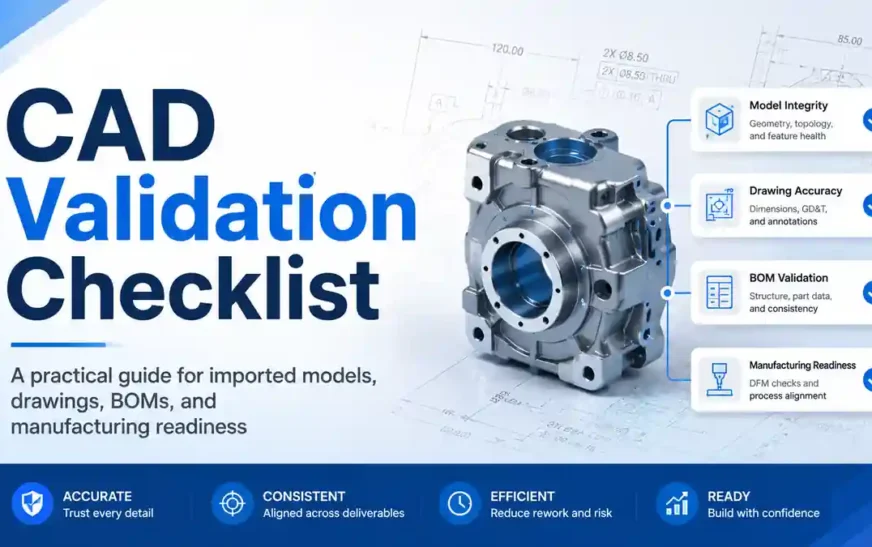
A CAD validation checklist helps engineers confirm whether a CAD model is complete, accurate, and safe to use before it enters assemblies, drawings, BOMs, manufacturing, or release workflows.
In mechanical design, a CAD model can look correct on screen and still contain hidden problems. The geometry may rotate properly. The file may open without crashing. The shape may visually match the requirement. But that does not always mean the model is reliable for real engineering work.
A downloaded, imported, migrated, or reused CAD file may still have missing references, broken links, faulty imported geometry, wrong units, incorrect custom properties, wrong configurations, broken drawing views, BOM mismatches, or missing manufacturing information.
These issues usually appear late, when the design is already inside a larger assembly, when the drawing is being released, when the BOM is sent to purchase, or when manufacturing starts asking questions. By that time, the cost of correction becomes much higher.
That is why CAD validation should not be treated as an optional final check. It should be a normal engineering habit.
This article provides a practical CAD validation checklist for mechanical design engineers, CAD engineers, SOLIDWORKS users, manufacturing teams, CAD migration teams, and anyone working with 3D models, 2D drawings, BOMs, or engineering documentation.
It is not written only for one software or one file format. The principles apply to native CAD files, imported STEP files, IGES files, Parasolid files, supplier CAD models, customer data, converted CAD files, and old project files reused in new designs.
What Is a CAD Validation Checklist?
A CAD validation checklist is a structured list of checks used to confirm whether a CAD file is ready for engineering use.
It is not only a geometry check. A useful CAD validation checklist also reviews file structure, references, units, material, mass properties, configurations, custom properties, drawings, BOMs, manufacturing information, and revision clarity.
In simple terms, CAD validation answers one important question:
Can this CAD file be trusted for the next engineering step?
That next step may be assembly design, drawing creation, BOM generation, design review, tooling, fabrication, machining, sheet metal flat pattern creation, procurement, simulation, or release to production.

A model that only looks correct is not always ready. A model is ready only when the data behind it is also reliable.
Why CAD Validation Matters in Mechanical Design
Mechanical design is not only about creating shapes. It is about creating usable engineering information.
A CAD model often becomes the source for many downstream activities:
- Assembly structure
- 2D drawings
- BOM tables
- Part numbers
- Material information
- Manufacturing notes
- Weight calculation
- Purchased component identification
- Revision control
- PDM or PLM workflows
- Supplier communication
- Inspection and quality review
If the CAD data is wrong, many connected outputs can also become wrong.

For example, if a part file has the wrong custom property, the drawing title block may show incorrect information. If an assembly has missing references, the BOM may be incomplete. If a STEP file has bad imported geometry, section views or manufacturing operations may fail. If a sheet metal model cannot create a flat pattern, it is not ready for fabrication even if the folded model looks good.
Here is a simple example:
| CAD Issue | Possible Impact |
|---|---|
| Missing assembly reference | Incomplete assembly or wrong BOM |
| Wrong units | Oversized or undersized component |
| Faulty imported body | Drawing, section, machining, or simulation issue |
| Missing custom properties | Incorrect title block or BOM data |
| Wrong configuration | Wrong part released or purchased |
| Broken drawing view | Manufacturing misunderstanding |
| Poor file naming | Revision confusion and duplicate data |
A CAD validation checklist reduces these risks by forcing the engineer to check the model before trusting it.
CAD Validation Checklist Overview
A good CAD validation process should move from basic file checks to deeper engineering checks.
The process can be divided into eight stages:
| Stage | Validation Area | Purpose |
| 1 | File and source check | Understand what type of data you received |
| 2 | Folder and reference check | Confirm that linked files are available |
| 3 | Geometry check | Confirm solid body, surface, and import quality |
| 4 | Unit and orientation check | Avoid scale and placement mistakes |
| 5 | Metadata check | Confirm properties, material, and revision data |
| 6 | Assembly check | Validate mates, components, and structure |
| 7 | Drawing and BOM check | Confirm documentation readiness |
| 8 | Manufacturing check | Confirm release and production readiness |
This CAD validation checklist can be used manually for one file or converted into an automated workflow for large projects.
1. Check File Type and Source
The first step is to understand what type of CAD file you are dealing with.
A native CAD file may contain feature history, configurations, custom properties, mates, drawings, design tables, and references. A neutral file such as STEP, IGES, Parasolid, or SAT may only contain imported geometry. A drawing file may depend on a model file that is not included. A ZIP folder may contain a full project package, but it may also contain missing or duplicate files.
Common file types include:
- SLDPRT for SOLIDWORKS part files
- SLDASM for SOLIDWORKS assembly files
- SLDDRW for SOLIDWORKS drawing files
- STEP or STP for neutral 3D exchange
- IGES or IGS for surface or geometry exchange
- X_T or X_B for Parasolid files
- SAT for ACIS files
- DWG or DXF for 2D drawing or profile data
- ZIP folders containing multiple linked files
Before editing the model, ask:
- Where did the file come from?
- Is it supplier data, customer data, online data, internal data, or migrated data?
- Is it native CAD or neutral CAD?
- Is the file the latest revision?
- Is a backup copy available?
- Is the file approved for reuse?
Never start by editing the only available copy. Keep the original file separately and validate a working copy.
2. Check Folder Structure
Poor folder structure is one of the most common causes of missing references and broken drawing links.
Assemblies and drawings often depend on many related files. If those files are scattered across different folders, copied from old locations, renamed manually, or mixed with older revisions, the CAD system may not find them correctly.
A clean project package may include:
- Parts
- Assemblies
- Drawings
- Purchased components
- Reference files
- Exported files
- PDFs
- BOM files
- Manufacturing documents
A folder does not need to be complex. It needs to be understandable.
Check the following:
- Are all part files available?
- Are all assembly files available?
- Are all drawing files available?
- Are reference files stored in the expected location?
- Are duplicate file names present?
- Are old revisions mixed with latest files?
- Are file names meaningful?
- Are files still inside the Downloads folder?
- Is the project folder ready for long-term storage?
Avoid names such as Part1, Assembly1, Final, New, Latest, Updated, Copy, Trial, or Test unless they are temporary working files.
Poor file organization may not look like an engineering issue at first. But later it can create BOM mistakes, drawing reference errors, and revision confusion.
3. Check Opening Warnings
When opening a CAD file, warning messages should not be ignored.
Many engineers click through warnings quickly because they want to see the model. That is risky. Opening warnings often tell you exactly what is wrong with the file.
Typical warnings include:
- Unable to locate file
- Missing component
- File contains invalid geometry
- Import diagnostics required
- References cannot be found
- Drawing view is out of date
- Lightweight components need resolving
- Model has rebuild errors
- Future version file warning
- Design table or linked file not found
A warning is not just a software message. It is a validation signal.
Before saving the file, read the warning carefully. If the file is part of customer or supplier data, take screenshots or make notes. Saving too early may update references, change file paths, or hide the original problem.
Checklist:
- Did the file open without warnings?
- Were any components missing?
- Did the software ask for referenced files?
- Did the model show rebuild errors?
- Was import diagnostics suggested?
- Did the drawing show out-of-date views?
- Did you record the issue before saving?
If a model opens with warnings, do not treat it as approved data.
4. Check Missing Assembly References
Assemblies depend on part files. If even one required file is missing, the assembly may not represent the intended design.
A missing component can affect assembly layout, mate behavior, mass properties, drawing views, exploded views, and BOM quantity. In some cases, the assembly may still open, but the design meaning may be incomplete.
Common signs of missing references include:
- Components missing from graphics area
- Warning icons in the feature tree
- Suppressed components that should be active
- Lightweight or unresolved components
- Failed mates
- Empty BOM rows
- Assembly rebuild errors
- Drawing views missing parts
Use a reference check before trusting the assembly.
Checklist:
- Does the assembly open without missing component warnings?
- Are all expected components visible?
- Are any components suppressed unintentionally?
- Are lightweight components resolved?
- Are mates failing because of missing files?
- Does the BOM show all expected items?
- Are all purchased components included?
- Was the assembly packaged correctly?
When sharing or archiving assembly data, use a complete packaging method rather than manually copying files one by one. This reduces the chance of missing references.
5. Check Broken External Links
External references can be useful in controlled design environments, but they can become risky when files are downloaded, copied, migrated, or moved.
External links may include:
- In-context assembly references
- Derived parts
- Inserted parts
- Linked sketches
- Linked equations
- Linked design tables
- Referenced images
- Decals or appearances
- Drawing model references
- Simulation files
- Tooling or fixture references
The problem is not that external references exist. The problem is when they are unknown, uncontrolled, or broken.
Checklist:
- Does the model depend on files outside the current project folder?
- Are linked design tables available?
- Are in-context references still valid?
- Are linked sketches or inserted parts available?
- Are drawing views linked to correct model files?
- Are broken references documented?
- Should references be preserved, locked, or removed?
Do not break external references blindly. First understand whether they represent important design intent.
For production workflows, uncontrolled external links can create future rebuild failures and revision confusion.
6. Check Imported Geometry Quality
Imported files require special attention.
A STEP, IGES, Parasolid, or SAT file may lose original feature history during translation. The model may come in as an imported body. It may look complete, but it can contain gaps, faulty faces, open edges, short edges, or surface problems.
Common imported geometry issues include:
- Faulty faces
- Gaps between surfaces
- Open edges
- Surface bodies instead of solid bodies
- Failed knit operations
- Imported body errors
- Short edges
- Sliver faces
- Non-manifold conditions
- Missing small features
- Geometry that cannot be sectioned cleanly
Checklist:
- Is the imported model a valid solid body?
- Are there faulty faces?
- Are there open edges?
- Are there gaps between surfaces?
- Did import diagnostics report errors?
- Can the model be sectioned?
- Does it rebuild without errors?
- Can key faces and edges be selected properly?
- Are important holes and surfaces intact?
A model that looks good visually may still be unsuitable for drawings, machining, simulation, or modification.
This is especially important for CAD migration projects. File conversion alone is not enough. Converted files should be checked for geometry quality before release.
7. Check Solid and Surface Body Quality
After checking import errors, review the body structure.
A typical manufactured mechanical component should usually be a valid solid body. Surface bodies may be correct in some design workflows, but for many production parts, a clean solid body is expected.
Check the body folders:
- Solid Bodies
- Surface Bodies
- Imported Bodies
- Cut List items
- Hidden bodies
- Multibody structure
Checklist:
- Is the main model a solid body?
- Are there unwanted surface bodies?
- Are there hidden bodies?
- Are there multiple bodies when only one is expected?
- Are bodies named clearly?
- Are weldment cut list bodies correct?
- Does the model rebuild cleanly?
- Does the section view show valid geometry?
- Are there tiny unwanted bodies from import errors?
A part may be visually correct but internally messy. Body quality affects drawings, mass properties, manufacturing, automation, and downstream modification.
8. Check Units and Scale
Wrong units can create serious engineering mistakes.
A file created in inches may be imported as millimeters. A supplier file may use the correct shape but the wrong scale. A downloaded model may not match the expected datasheet size.
Do not assume the scale is correct.
Measure basic dimensions:
- Overall length
- Overall width
- Overall height
- Hole diameter
- Shaft diameter
- Plate thickness
- Wall thickness
- Mounting distance
- Critical interface dimensions
Checklist:
- Are document units correct?
- Is the model in millimeters, inches, or another unit?
- Do overall dimensions match the expected size?
- Are hole sizes correct?
- Is thickness realistic?
- Does mass look reasonable?
- Does the model match supplier or project data?
Unit errors can quietly move into drawings, BOMs, manufacturing, purchase orders, and assembly layouts. A simple measurement check can prevent major mistakes.
9. Check Orientation and Origin
Orientation and origin may look like small details, but they affect daily CAD work.
A poorly oriented model can cause problems during assembly insertion, drawing view creation, machining setup, automation, and coordinate-based downstream workflows.
Checklist:
- Is the model aligned with front, top, and right views?
- Is the origin placed logically?
- Is the main axis aligned properly?
- Is the model far away from the origin?
- Is a coordinate system required?
- Does the model insert cleanly into an assembly?
- Are drawing views meaningful without manual rotation?
- Is the part suitable for automation or batch processing?
A model placed far from the origin can create drawing and assembly handling issues. A model with poor orientation can make standard views confusing.
Good orientation improves reuse, documentation, collaboration, and automation.
10. Check Material and Mass Properties
Material is not just visual appearance.
A model may look like steel, aluminum, plastic, or rubber because of color or rendering appearance. That does not mean the correct engineering material is assigned.
Material affects:
- Weight
- Center of gravity
- Cost estimation
- Simulation
- Manufacturing process
- Drawing notes
- BOM information
- Design review decisions
Checklist:
- Is material assigned?
- Is the material correct?
- Is density correct?
- Is mass reasonable?
- Is volume reasonable?
- Is center of gravity reasonable?
- Is material linked to custom properties?
- Is the material unknown and marked for review?
Mass properties are also useful for catching hidden problems. If the mass is unrealistic, check units, body quality, and material assignment again.
Do not guess material if it is unknown. Mark it clearly and confirm before release.
11. Check Custom Properties
Custom properties are the connection between CAD geometry and engineering documentation.
A part may be geometrically correct but still not ready for drawing or BOM release if the properties are missing.
Important custom properties may include:
- Part Number
- Description
- Material
- Revision
- Weight
- Finish
- Drawn By
- Checked By
- Approved By
- Project Name
- Vendor
- Manufacturing Process
- Treatment
- Stock Size
- Make or Buy
- Category
Checklist:
- Are required properties filled?
- Are property names standardized?
- Are configuration-specific properties correct?
- Is the part number correct?
- Is the description meaningful?
- Is material linked correctly?
- Is revision clear?
- Does the drawing title block read the correct values?
- Does the BOM table show the correct values?
Missing or inconsistent properties create drawing and BOM problems. This is one of the best areas for CAD automation because property checks can often be scanned across many files.
12. Check Configurations and Revisions
Configurations are powerful, but they can also create release risk.
A file may contain multiple configurations for size variations, design options, simplified states, manufacturing states, purchased versions, or old revisions. If the wrong configuration is active in the drawing or BOM, the wrong part may be released.
Checklist:
- How many configurations exist?
- Which configuration is active?
- Is the active configuration the correct one?
- Do all configurations rebuild cleanly?
- Are suppressed features intentional?
- Are configuration-specific properties correct?
- Does the drawing use the correct configuration?
- Does the BOM use the correct configuration?
- Does the revision match file name, property, and drawing?
Never assume the visible model is the released model. Confirm the configuration.
Revision control should also be checked carefully. File name, custom property, drawing revision table, and released PDF should not contradict each other.
13. Check Assembly Mates and Constraints
If the CAD file is an assembly, mate health is a critical part of validation.
An assembly can look correct in a fixed position while still containing failed, over-defined, or missing mates. This becomes a problem when the assembly is moved, updated, copied, or used in a drawing.
Checklist:
- Are mates solved?
- Are there over-defined mates?
- Are mate references missing?
- Are components fixed unintentionally?
- Are flexible components behaving correctly?
- Are moving parts constrained correctly?
- Are standard parts placed correctly?
- Does the assembly rebuild cleanly?
- Does the assembly move as intended?
- Are exploded views still valid?
Good assembly structure is not only about visual position. It is about controlled behavior.
Poor mate quality can lead to unstable assemblies, drawing changes, and confusion during design updates.
14. Check Sheet Metal Usability
Sheet metal models need their own validation.
A part may look like sheet metal, but it may not behave like a proper sheet metal model. For manufacturing, the flat pattern is often as important as the folded model.
Checklist:
- Is the part recognized as sheet metal?
- Is thickness consistent?
- Are bends recognized?
- Is bend radius correct?
- Can a flat pattern be generated?
- Are bend reliefs available?
- Are cutouts manufacturable?
- Are bend directions correct?
- Is the flat pattern clean?
- Are manufacturing notes required?
A sheet metal part that cannot generate a correct flat pattern is not ready for fabrication.
This is a common issue with imported sheet metal files. The shape may look right, but the CAD system may not understand it as sheet metal.
15. Check Holes, Threads, and Standard Features
Holes, threads, slots, keyways, and standard features must be checked carefully because they directly affect assembly and manufacturing.
Downloaded or imported models sometimes simplify these features. Threads may be cosmetic. Holes may be approximate. Counterbores may be missing. Mounting patterns may not match the actual hardware.
Checklist:
- Are hole sizes correct?
- Are counterbores correct?
- Are countersinks correct?
- Are threaded holes represented properly?
- Are clearance holes suitable for fasteners?
- Are hole patterns correct?
- Are shaft fits verified?
- Are keyways and slots correct?
- Are standard components properly matched?
- Are manufacturing callouts required?
A visually correct hole can still be wrong for production.
Before releasing a drawing or using the model in an assembly, verify functional features against design requirements, datasheets, or manufacturing standards.
16. Check BOM Readiness
A model is not BOM-ready just because it opens.
BOM readiness depends on correct structure, properties, quantities, configurations, and part classification.
BOM mistakes can affect purchasing, cost, inventory, manufacturing, and project delivery.
Checklist:
- Are part numbers complete?
- Are descriptions clear?
- Are quantities correct?
- Are purchased parts identified?
- Are fabricated parts identified?
- Are suppressed components excluded correctly?
- Are virtual components handled properly?
- Are duplicate parts controlled?
- Are configurations mapped correctly?
- Are weldment cut list properties complete?
- Are make-or-buy decisions clear?
A BOM should represent what the team actually needs to manufacture, purchase, assemble, and release.
If the CAD structure is wrong, the BOM will also be wrong.
17. Check Drawing Integrity
Drawings must be validated separately from 3D models.
A model may be correct, but the drawing may still contain broken views, dangling dimensions, missing annotations, wrong title block values, or outdated BOM tables.
Common drawing problems include:
- Broken drawing views
- Missing model references
- Dangling dimensions
- Detached annotations
- Out-of-date views
- Wrong scale
- Empty BOM table
- Incorrect title block values
- Missing revision details
- Wrong sheet format
- Broken section views
- Missing flat pattern view
- Incorrect view configuration
Checklist:
- Do all drawing views rebuild?
- Are any views broken?
- Are dimensions still attached?
- Are annotations correct?
- Is the BOM table correct?
- Is the title block populated?
- Is the revision table correct?
- Are all sheets updated?
- Is the drawing using the correct configuration?
- Is the PDF output clean?
A drawing should not be released only because the model looks correct. Drawing validation is its own responsibility.
18. Check Manufacturing Readiness
Engineering CAD data becomes useful only when it supports manufacturing or downstream decision-making.
A model may be acceptable for concept design but not ready for production. Manufacturing readiness depends on geometry, dimensions, tolerances, material, finish, process notes, and supplier clarity.
Checklist:
- Are critical dimensions available?
- Are tolerances defined?
- Is material confirmed?
- Is finish specified?
- Are weld notes required?
- Are bend notes required?
- Are machining allowances considered?
- Are inspection requirements clear?
- Are purchased items separated?
- Are manufacturing processes understood?
- Are revision details clear?
A CAD validation checklist should always include manufacturing readiness because that is where many hidden CAD problems become real cost.
CAD is not only for design. It is part of the design-to-manufacturing chain.
19. Check File Naming and Revision Control
File naming looks simple, but poor naming can create major confusion.
Bad naming causes duplicate files, wrong references, revision mismatch, and release mistakes.
Avoid file names such as:
- Part1
- Assembly1
- Final
- Final_New
- Latest
- Latest_Final
- Copy
- Updated
- New
- Trial
- Test
Checklist:
- Is the file name meaningful?
- Is the part number included if required?
- Are duplicate names avoided?
- Is revision handled consistently?
- Are drawings, parts, and assemblies aligned?
- Is the latest version identifiable?
- Are old files archived properly?
- Is naming compatible with PDM or document control rules?
Good file naming supports long-term data quality.
If a file cannot be identified confidently, it should not be released confidently.
20. Check Reuse Risk Before Using Old CAD Data
Old CAD data can be useful, but it should not be reused blindly.
A previous project file may contain old design assumptions, outdated material, obsolete supplier information, old tolerances, old revision status, or project-specific decisions that do not apply anymore.
Checklist:
- Why is this old file being reused?
- Was it previously released?
- Is the revision still valid?
- Are supplier details still current?
- Are material and finish still acceptable?
- Are old project notes still relevant?
- Are custom properties updated?
- Are drawing templates current?
- Are old references removed?
Reusing old CAD files can save time, but only when the file is validated before reuse.
21. Check Release Readiness
The final step is to confirm whether the CAD data is ready for release or only ready for internal review.
Release-ready data should be complete, clear, and controlled.
Checklist:
- Model opens without major errors
- Assembly references are complete
- Geometry is valid
- Units and scale are correct
- Material is confirmed
- Properties are complete
- Configuration is correct
- BOM is accurate
- Drawings are clean
- Manufacturing information is available
- Revision is clear
- File naming is controlled
- Required approvals are complete
Not every model needs to be production-ready. Some models are only for concept, layout, quotation, simulation, or reference. But the file status should be clear.
A simple label such as Concept, Reference Only, For Review, Prototype, or Released can prevent misuse.
Final CAD Validation Checklist Table
Use this table as a quick reference before approving a downloaded, imported, migrated, or reused CAD model.
| Validation Area | What to Check | Why It Matters |
| File Type | Native or neutral CAD | Defines editability and risk |
| Source | Supplier, customer, internal, online, migrated | Helps judge reliability |
| Folder Structure | Complete package | Prevents missing references |
| Opening Warnings | Missing files, invalid geometry, rebuild errors | Identifies early risk |
| Assembly References | Components and linked files | Prevents incomplete assemblies |
| External Links | Broken dependencies | Avoids future rebuild failures |
| Imported Geometry | Faulty faces, gaps, open edges | Prevents downstream errors |
| Body Quality | Solid body, surface body, hidden bodies | Supports drawings and manufacturing |
| Units and Scale | Dimensions and document units | Avoids size mistakes |
| Orientation | Origin and standard views | Improves reuse and automation |
| Material | Material, density, mass | Supports weight and manufacturing |
| Custom Properties | Part number, description, revision | Supports BOM and drawings |
| Configurations | Correct active configuration | Prevents wrong release |
| Assembly Mates | Solved and stable constraints | Ensures assembly behavior |
| Sheet Metal | Thickness, bends, flat pattern | Supports fabrication |
| Holes and Threads | Functional features | Prevents assembly and machining issues |
| BOM | Quantities and part numbers | Supports purchasing and manufacturing |
| Drawing | Views, dimensions, title block | Supports production documentation |
| Manufacturing | Tolerances, finish, process notes | Supports release readiness |
| Revision Control | File name, property, drawing revision | Prevents wrong version use |
| Release Status | Review, reference, concept, released | Prevents misuse |
How CAD Validation Can Be Automated
Manual validation is useful, especially for one-time checks. But when a team handles hundreds or thousands of CAD files, manual checking becomes slow and inconsistent.
This is where CAD automation becomes valuable.
A CAD validation checklist can be converted into automation rules. A macro, API tool, or batch validation utility can scan files and report common issues.
Automation can help check:
- Missing custom properties
- Empty part numbers
- Material assignment
- Wrong revision fields
- File naming issues
- Drawing title block data
- BOM table presence
- Missing drawing views
- Configuration list
- Sheet metal flat pattern status
- Assembly reference paths
- Export status
- PDF availability
- File type and folder structure
But automation should not be built only to save clicks.
A good CAD automation tool should also reduce engineering risk. It should produce a clear report, show which files passed, identify which files failed, and explain what needs manual review.
This is the idea behind validation-first CAD automation.
The goal is not just faster CAD work. The goal is more reliable CAD work.
For example, a macro that exports PDFs is useful. But a macro that checks drawing references, title block properties, missing BOM data, and then exports PDFs is much more valuable.
Speed matters. But validation matters more.
CAD Validation for Migration Projects
CAD migration is one of the most important use cases for this checklist.
When files are converted from one CAD system to another, the visible shape is only one part of the result. The migration must also be checked for references, assemblies, drawings, properties, sheet metal behavior, BOM readiness, and manufacturing usability.
A converted file should be checked for:
- Imported body quality
- Missing assembly references
- Lost custom properties
- Drawing link issues
- Configuration mismatch
- Revision mismatch
- Broken external links
- Sheet metal flat pattern usability
- BOM consistency
- File naming and folder structure errors


CAD migration is not just file conversion.
A successful migration means the converted data can be trusted in real engineering work.
That is why migration validation should be treated as a sub-area of the broader CAD validation checklist.
CAD Validation for Downloaded Models
Downloaded CAD models from online libraries or supplier websites can save time, but they should not be trusted automatically.
A supplier model may be simplified. An online model may have wrong dimensions. A downloaded assembly may be missing parts. A neutral file may contain poor imported geometry. A model may not have material, custom properties, or correct orientation.
Before using downloaded CAD models, check:
- Source reliability
- File type
- Units
- Overall dimensions
- Material
- Body quality
- Holes and mounting interfaces
- Assembly references
- Simplification level
- Manufacturing relevance
A downloaded model is useful as a starting point, not as an automatically approved engineering file.
CAD Validation for Drawings and BOMs
Drawings and BOMs are where CAD data becomes communication.
A drawing tells manufacturing what to make. A BOM tells purchase and production what is required. If CAD properties, configurations, or references are wrong, drawing and BOM outputs can become wrong.
Check drawings and BOMs together.
For drawings, confirm:
- Views are not broken
- Dimensions are attached
- Notes are correct
- Title block values are correct
- Revision table is updated
- Scale and sheet format are correct
- PDF export is clean
For BOMs, confirm:
- Part numbers are correct
- Quantities are correct
- Descriptions are clear
- Purchased parts are identified
- Fabricated parts are identified
- Suppressed components are handled correctly
- Configurations are mapped correctly
A clean CAD model should create clean documentation.
FAQ on CAD validation checklist
1. What is a CAD validation checklist?
A CAD validation checklist is a structured set of checks used to confirm whether a CAD model is complete, accurate, and ready for engineering use. It helps engineers review geometry, file references, units, material, custom properties, configurations, drawings, BOMs, and manufacturing readiness before using or releasing a CAD file.
2. Why is a CAD validation checklist important?
A CAD validation checklist is important because a model can look correct on screen but still contain hidden problems. Missing references, wrong units, faulty imported geometry, incorrect properties, broken drawing views, and BOM mismatches can create rework, manufacturing confusion, and release errors.
3. When should engineers use a CAD validation checklist?
Engineers should use a CAD validation checklist before using downloaded models, imported STEP or IGES files, migrated CAD data, supplier models, customer files, reused old project files, or any CAD file that will be used in assemblies, drawings, BOMs, manufacturing, or release workflows.
4. What should be checked in a CAD model before using it?
Before using a CAD model, check the file type, folder structure, missing references, external links, imported geometry quality, solid body status, units, scale, orientation, material, mass properties, custom properties, configurations, assembly mates, BOM data, drawing views, and manufacturing readiness.
5. Is CAD validation only about checking geometry?
No. CAD validation is not only about geometry. Geometry quality is important, but a complete CAD validation checklist also includes references, file naming, custom properties, configurations, material, mass properties, drawings, BOMs, revision control, and manufacturing information.
6. Should downloaded CAD models be validated?
Yes. Downloaded CAD models should always be validated before use. A downloaded model may have wrong dimensions, missing material, poor imported body quality, simplified features, incorrect orientation, missing references, or no custom properties. It should be treated as reference data until verified.
7. How is CAD validation different from CAD migration validation?
CAD validation is the broader process of checking any CAD file before use or release. CAD migration validation is a specific part of CAD validation that focuses on checking converted or migrated CAD files after moving data from one CAD system or format to another.
8. What are common problems in imported CAD files?
Common problems in imported CAD files include faulty faces, open edges, surface gaps, missing features, surface bodies instead of solid bodies, wrong units, poor body quality, lost custom properties, missing assembly references, and drawing or BOM link issues.
9. Can CAD validation be automated?
Yes. Many CAD validation checks can be automated using CAD APIs, macros, or batch tools. Automation can check missing properties, file naming, material assignment, configurations, drawing data, BOM presence, reference paths, export status, and folder structure. However, engineering judgment is still needed for design intent and manufacturing decisions.
10. What is validation-first CAD automation?
Validation-first CAD automation is an approach where automation is designed not only to save time, but also to check engineering quality. Instead of simply running a macro faster, the workflow validates references, properties, drawings, BOMs, configurations, and output quality before files are used or released.
Related References
- Why CAD Automation Fails
- AI-Powered Engineering Systems
- CAD Automation Systems
- Bend Allowance Calculator