

What Is the CAD Automation Ecosystem?
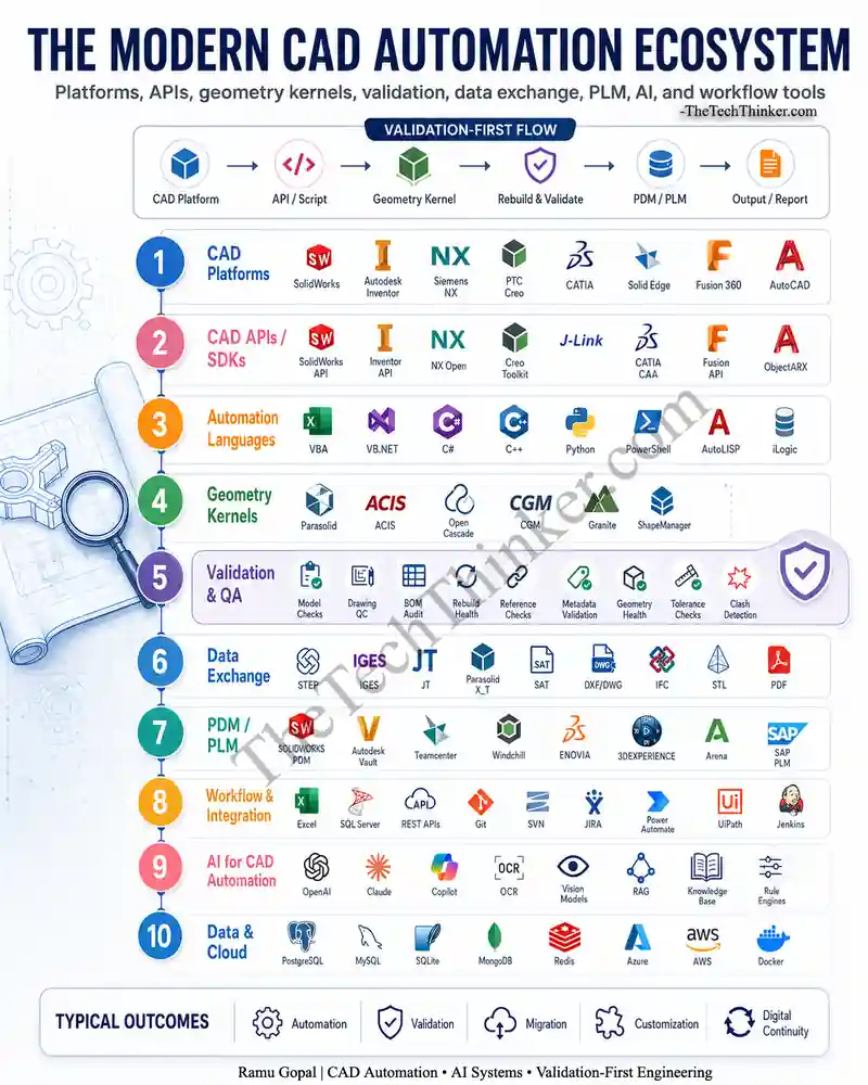
The CAD Automation Ecosystem is the complete set of platforms, programming interfaces, automation languages, geometry engines, validation methods, data formats, PDM/PLM systems, workflow tools, and AI systems used to automate engineering design processes.
In simple terms, it connects:
- CAD platforms
- CAD APIs and SDKs
- Automation languages
- Geometry kernels
- Drawing and model validation
- BOM and metadata checks
- Data exchange formats
- PDM and PLM systems
- Workflow integration tools
- AI-assisted engineering tools
- Databases and cloud platforms
Most engineers first understand CAD automation through macros.
For example:
- A SolidWorks VBA macro to update custom properties
- An Inventor iLogic rule to control parameters
- An AutoLISP script to clean drawings
- A Python script to process exported files
- A C# add-in to automate repetitive CAD tasks
These are useful starting points. But the CAD Automation Ecosystem becomes more powerful when these scripts are connected with validation, reporting, revision control, PDM/PLM, and downstream manufacturing workflows.
Official CAD API documentation also reflects this broader automation direction. For example, SOLIDWORKS describes its API as a way to automate and customize the software, and Autodesk provides Inventor API resources including developer guides and object model references.
Why CAD Automation Is Bigger Than Macros
Macros are only one layer of the CAD Automation Ecosystem.
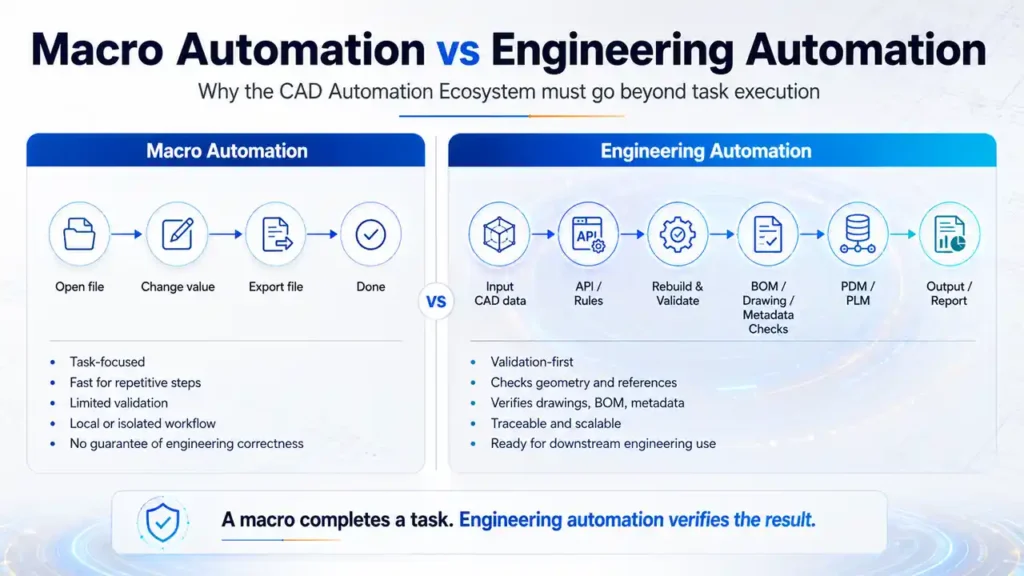
A macro usually focuses on execution:
- Open file
- Read parameter
- Change dimension
- Update property
- Export PDF
- Save STEP
- Close file
But engineering automation must focus on both execution and correctness.
A professional CAD automation workflow should also check:
- Did the model rebuild without errors?
- Are all external references valid?
- Are configurations updated correctly?
- Are drawing views still attached?
- Are dimensions and annotations still meaningful?
- Is the BOM consistent with the model?
- Are custom properties complete?
- Is the revision information correct?
- Is the exported file usable downstream?
- Is the final output traceable?
This is where many automation projects fail.
They automate the action but ignore the result.
The CAD Automation Ecosystem should not stop at “task completed.” It should move toward “engineering output verified.”
The Validation-First Flow in CAD Automation
A strong CAD Automation Ecosystem follows a validation-first flow.
CAD Platform → API / Script → Geometry Kernel → Rebuild & Validate → PDM / PLM → Output / Report
This flow is important because every CAD automation task touches engineering data.
A simple export macro may look harmless. But if the input model has suppressed features, broken references, outdated configurations, missing properties, or failed rebuilds, the final output may become unreliable.
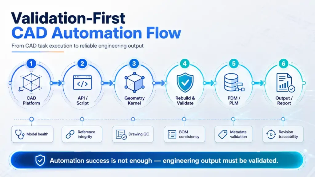
A practical validation-first workflow includes:
- Open the CAD file safely
- Identify document type: part, assembly, or drawing
- Read configurations and custom properties
- Check rebuild status
- Check missing references
- Validate geometry health
- Validate drawing sheets and views
- Validate BOM and revision data
- Generate output files
- Create a validation report
- Store or release data through PDM/PLM
This is the point where CAD automation becomes engineering automation.
10 Layers of the Modern CAD Automation Ecosystem
1. CAD Platforms
CAD platforms are the base layer of the CAD Automation Ecosystem.
Common platforms include:
- SolidWorks
- Autodesk Inventor
- Siemens NX
- PTC Creo
- CATIA
- Solid Edge
- Fusion 360
- AutoCAD
- Revit
- Tekla Structures
Each platform has its own data structure, object model, feature tree, drawing environment, assembly behavior, and customization method.
A CAD developer must understand not only the API syntax, but also how the CAD platform thinks.
For example:
- A part file is not the same as an assembly file.
- A drawing view depends on a model reference.
- A configuration can change geometry and BOM output.
- A suppressed feature can affect downstream validation.
- A derived or imported body may behave differently from a native parametric feature.
This is why CAD automation requires engineering understanding, not only programming knowledge.
2. CAD APIs and SDKs
CAD APIs and SDKs are the access points for automation.
They allow developers to control CAD software programmatically.
Common examples include:
- SolidWorks API
- Inventor API
- NX Open
- Creo Toolkit
- J-Link
- CATIA CAA
- Solid Edge API
- Fusion API
- ObjectARX
- Revit API
These APIs help developers automate:
- Model creation
- Feature editing
- Assembly traversal
- Drawing generation
- BOM extraction
- Custom property updates
- File conversion
- Configuration control
- Quality checks
- Report generation
For high-end CAD development roles, knowledge of C++, C#, geometry, and CAD APIs becomes highly valuable. Open CASCADE, for example, is described as a C++ class library for building CAD/CAM/CAE applications, showing how CAD automation can move beyond simple scripting into engineering software development.
3. Automation Languages
The CAD Automation Ecosystem uses different programming languages depending on the platform, complexity, and deployment requirement.
Common languages include:
- VBA
- VB.NET
- C#
- C++
- Python
- PowerShell
- AutoLISP
- iLogic
Each language has a different role.
VBA
VBA is widely used for quick CAD macros, especially in SolidWorks and Excel-connected workflows.
C# and VB.NET
C# and VB.NET are useful for professional add-ins, Windows applications, database connections, and enterprise-level automation tools.
C++
C++ is important for deeper CAD development, geometric algorithms, performance-heavy tasks, and kernel-level applications.
Python
Python is useful for automation pipelines, data processing, AI integration, file handling, and batch workflows.
AutoLISP and iLogic
AutoLISP is common in AutoCAD automation. iLogic is useful for rule-based Inventor automation.
A strong CAD developer does not need to master every language. But understanding where each language fits inside the CAD Automation Ecosystem helps in choosing the right tool for the right task.
4. Geometry Kernels
Geometry kernels are the invisible engines behind CAD systems.
They manage:
- Curves
- Surfaces
- Solids
- Topology
- Boolean operations
- Fillets
- Shells
- Intersections
- B-rep data
- Model healing
Important geometry kernels include:
- Parasolid
- ACIS
- Open Cascade
- CGM
- Granite
- ShapeManager
This layer is critical because CAD automation is not just about moving files. It often deals with geometric truth.
A CAD model may look correct on screen, but automation must still consider:
- Is the body valid?
- Are there open edges?
- Are faces corrupted?
- Did the import create surface bodies instead of solids?
- Are there tolerance gaps?
- Can the body be used for downstream operations?
- Will the exported model survive another CAD system?
This is where geometry knowledge becomes a serious advantage.
5. Validation and QA
Validation is the most important layer of the CAD Automation Ecosystem.
Without validation, automation can create faster mistakes.
A validation-first approach checks whether the output is technically acceptable before it is released, exported, or passed downstream.
Key CAD validation checks include:
- Model rebuild health
- Feature error checks
- Missing reference checks
- Drawing view reference checks
- BOM consistency checks
- Custom property validation
- Revision and state validation
- Sheet format and title block checks
- Flat pattern validation
- Hole callout validation
- Tolerance and annotation checks
- Geometry body health checks
- Clash and interference checks
- File naming checks
- Output file completeness checks
Why validation matters
A CAD automation tool may generate 500 PDFs in one hour. But if 50 drawings contain broken dimensions, the automation has created risk.
A tool may export 1,000 STEP files. But if some files have geometry errors or wrong configurations, downstream teams may face manufacturing or supplier issues.
A tool may update custom properties in bulk. But if revision and PDM state are not checked, released data can become inconsistent.
That is why validation should be treated as a core layer, not an optional feature.
6. Data Exchange
Data exchange connects CAD systems with suppliers, customers, manufacturing teams, simulation tools, and documentation systems.
Common formats include:
- STEP
- IGES
- JT
- Parasolid X_T
- SAT
- DXF/DWG
- IFC
- STL
STEP is especially important in mechanical CAD exchange. ISO 10303 defines principles for product information representation and exchange, and NIST describes STEP as broader than older pure geometry exchange approaches because it can cover product data across the lifecycle.
Data exchange automation should check:
- Correct format
- Correct configuration
- Correct file naming
- Correct revision
- Correct export options
- Correct destination folder
- Successful file creation
- File size and readability
- Downstream compatibility
A good CAD Automation Ecosystem does not simply export files. It validates whether the exchanged data is useful.
7. PDM and PLM
PDM and PLM systems bring control, traceability, and lifecycle management into CAD automation.
Common systems include:
- SOLIDWORKS PDM
- Autodesk Vault
- Teamcenter
- Windchill
- ENOVIA
- 3DEXPERIENCE
- Arena
- SAP PLM
PDM/PLM integration matters because engineering automation often touches controlled data.
A tool may need to:
- Check file state
- Read revision
- Validate lifecycle status
- Prevent modification of released files
- Update metadata
- Generate release packages
- Export approved documents
- Track change history
- Connect CAD data with ERP or manufacturing systems
Siemens describes Teamcenter as PLM software for planning, developing, and delivering products, which shows why CAD automation becomes more valuable when connected with lifecycle processes rather than isolated desktop macros.
8. Workflow and Integration
Workflow integration connects CAD automation with business systems and engineering operations.
Common tools and systems include:
- Excel
- SQL Server
- REST APIs
- Git
- SVN
- JIRA
- Power Automate
- UiPath
- Jenkins
- Email systems
- ERP systems
- Internal dashboards
This layer is important because CAD data rarely stays inside CAD.
A practical automation workflow may need to:
- Read Excel input
- Update CAD models
- Save files into PDM
- Export PDFs and STEP files
- Log status into SQL
- Send email reports
- Create JIRA tickets
- Trigger approval workflows
- Generate dashboards
- Store validation results
This is how the CAD Automation Ecosystem moves from a local macro to an enterprise engineering workflow.
9. AI for CAD Automation
AI is becoming a new support layer in the CAD Automation Ecosystem.
AI should not be treated as a replacement for CAD APIs or engineering validation. Instead, it can support automation by improving search, interpretation, documentation, and decision assistance.
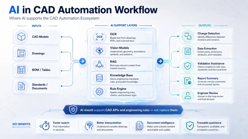
Possible AI use cases include:
- Drawing change detection
- OCR from title blocks and tables
- BOM comparison
- Engineering document search
- Rule-based validation assistance
- CAD knowledge assistants
- Natural language query for design data
- Automated report summarization
- Failure pattern detection
- RAG-based engineering knowledge retrieval
AI can help engineers understand engineering data faster. But final CAD validation should still be grounded in CAD API results, model state, geometry checks, and approved engineering rules.
AI should support, not blindly decide
A reliable AI-assisted CAD workflow should have:
- Clear input data
- Controlled prompts
- Verified CAD API outputs
- Human review for critical decisions
- Traceable references
- Validation reports
- Version-controlled rules
This is especially important in manufacturing, aerospace, automotive, industrial machinery, and regulated engineering environments.
10. Data and Cloud
The final layer of the CAD Automation Ecosystem is data infrastructure.
Common tools include:
- PostgreSQL
- MySQL
- SQLite
- MongoDB
- Redis
- Azure
- AWS
- Docker
Data and cloud systems help automation tools become scalable and maintainable.
They can store:
- File processing logs
- Validation results
- BOM comparison data
- User actions
- Error histories
- Rule libraries
- Job queues
- Dashboard data
- Audit trails
For small tools, a local CSV or SQLite database may be enough.
For enterprise tools, SQL databases, APIs, cloud storage, and containerized services may be required.
CAD Automation Ecosystem Toolchain Table
| Layer | Purpose | Example Tools | Engineering Value |
|---|---|---|---|
| CAD Platforms | Design authoring | SolidWorks, NX, Creo, Inventor | Native design control |
| CAD APIs / SDKs | Software access | SolidWorks API, NX Open, Inventor API | Automation and customization |
| Automation Languages | Logic and development | VBA, C#, C++, Python | Tool creation |
| Geometry Kernels | Shape computation | Parasolid, ACIS, Open Cascade | Geometry reliability |
| Validation and QA | Engineering checks | BOM audit, rebuild check, drawing QC | Risk reduction |
| Data Exchange | Neutral output | STEP, IGES, JT, PDF | Supplier and downstream use |
| PDM / PLM | Lifecycle control | Teamcenter, Vault, PDM | Traceability |
| Workflow Integration | Process connection | Excel, SQL, REST, JIRA | Enterprise automation |
| AI for CAD Automation | Assisted intelligence | OCR, RAG, vision models | Faster interpretation |
| Data and Cloud | Storage and scale | PostgreSQL, Azure, AWS | Scalable systems |
Where AI Fits in CAD Automation
AI will not remove the need for CAD APIs, geometry kernels, or validation rules.
Instead, AI can make the CAD Automation Ecosystem more intelligent when used carefully.
Useful AI-assisted CAD automation examples:
- Extracting drawing notes using OCR
- Comparing old and new drawing revisions
- Summarizing validation reports
- Searching internal engineering standards
- Helping users understand API object models
- Generating first-draft automation logic
- Classifying errors from batch processing logs
- Detecting visual differences in drawings
- Creating natural language interfaces for engineering tools
But AI should not be the only source of truth for engineering release decisions.
A safe approach is:
- Use CAD API for actual model data.
- Use validation rules for engineering checks.
- Use AI for interpretation and assistance.
- Use reports for traceability.
- Use human review for critical output.
That is the realistic future of AI in the CAD Automation Ecosystem.
Common Mistakes in CAD Automation Projects
Many CAD automation projects fail because they focus only on speed.
Common mistakes include:
- Automating without understanding the design process
- Ignoring rebuild errors
- Not checking missing references
- Exporting wrong configurations
- Trusting file creation without validating content
- Ignoring PDM state and revision
- Hardcoding paths and user names
- Not handling exceptions properly
- Not creating logs
- Not giving users a clear summary report
- Using AI output without engineering validation
- Building tools that work only on perfect test files
- Ignoring drawing-specific issues
- Not planning for future CAD version changes
A good CAD Automation Ecosystem should be designed for real engineering conditions, not only demo files.
How to Build a Practical CAD Automation Roadmap
A practical roadmap should start small and grow layer by layer.
Phase 1: Identify repetitive engineering tasks
Start with tasks such as:
- Property updates
- PDF export
- STEP export
- Drawing checks
- BOM extraction
- File renaming
- Batch conversion
- Template validation
Phase 2: Add validation
Add checks for:
- Rebuild errors
- Missing references
- Drawing view issues
- BOM mismatch
- Required properties
- Revision fields
- File naming rules
Phase 3: Add reporting
Every automation tool should produce:
- Success list
- Failed list
- Warning list
- Error reason
- File path
- Timestamp
- User action
- Output location
Phase 4: Connect with PDM/PLM
After the tool becomes stable, connect it with:
- File state
- Revision
- Approval workflow
- Release package
- Metadata sync
- Document control
Phase 5: Add AI carefully
Use AI for:
- Search
- Summaries
- OCR
- Drawing comparison
- Knowledge retrieval
- Error explanation
Do not use AI as an uncontrolled decision-maker for engineering release.
Final Thoughts
The CAD Automation Ecosystem is becoming a serious engineering software discipline.
It combines mechanical design knowledge, programming, CAD APIs, geometry understanding, validation logic, data exchange, PDM/PLM integration, AI assistance, and workflow automation.
The future of CAD automation is not only about faster macros.
It is about reliable engineering systems.
A strong CAD Automation Ecosystem should help teams:
- Save time
- Reduce repetitive work
- Improve design quality
- Prevent downstream errors
- Standardize engineering checks
- Improve data traceability
- Connect CAD with enterprise workflows
- Support validation-first product development
The real goal is simple:
Do not just automate the task. Validate the engineering result.
That is where CAD automation becomes engineering automation.
FAQs About CAD Automation Ecosystem
What is the CAD Automation Ecosystem?
The CAD Automation Ecosystem is the complete set of CAD platforms, APIs, programming languages, geometry kernels, validation tools, data exchange formats, PDM/PLM systems, AI tools, and workflow integrations used to automate engineering design processes.
Why is the CAD Automation Ecosystem important?
The CAD Automation Ecosystem is important because modern engineering automation must do more than complete repetitive tasks. It must also validate model health, drawing accuracy, BOM consistency, metadata, references, and downstream output quality.
Is CAD automation only about macros?
No. Macros are only one part of the CAD Automation Ecosystem. Professional CAD automation also includes APIs, add-ins, geometry validation, PDM/PLM integration, reporting, data exchange, and enterprise workflow automation.
Which programming languages are useful for CAD automation?
Common CAD automation languages include VBA, C#, VB.NET, C++, Python, AutoLISP, PowerShell, and iLogic. The best language depends on the CAD platform, project complexity, deployment method, and integration requirement.
What are CAD APIs?
CAD APIs are programming interfaces that allow developers to automate and customize CAD software. Examples include SolidWorks API, Inventor API, NX Open, Creo Toolkit, CATIA CAA, Fusion API, ObjectARX, and Revit API.
Why are geometry kernels important in CAD automation?
Geometry kernels handle curves, surfaces, solids, topology, Boolean operations, and model validity. In the CAD Automation Ecosystem, geometry kernels are important because automation often depends on whether the CAD body is mathematically valid and usable downstream.
What is validation-first CAD automation?
Validation-first CAD automation means checking the engineering correctness of the output before considering the automation successful. It includes rebuild checks, reference checks, drawing QC, BOM validation, metadata checks, geometry health checks, and output verification.
How does PDM/PLM fit into the CAD Automation Ecosystem?
PDM and PLM systems manage file state, revision, lifecycle, metadata, approvals, and traceability. In the CAD Automation Ecosystem, they help ensure that automation works with controlled engineering data instead of unmanaged local files.
Can AI be used in CAD automation?
Yes. AI can support CAD automation through OCR, drawing comparison, RAG-based engineering search, report summarization, knowledge assistants, and error interpretation. However, AI should support CAD API data and validation rules, not replace engineering checks.
What is the future of the CAD Automation Ecosystem?
The future of the CAD Automation Ecosystem will combine CAD APIs, geometry validation, PDM/PLM integration, workflow automation, AI-assisted engineering tools, and traceable validation reports to create more reliable engineering automation systems.
External Reference
- SOLIDWORKS API Help for CAD API reference.
- Autodesk Inventor API documentation for Inventor automation and object model learning.
- Open CASCADE documentation for geometry kernel and CAD/CAM/CAE application development.
- ISO 10303 / STEP overview for product data exchange fundamentals.
- Siemens Teamcenter page for PLM context.